This project was built for my introductory electronics class at the University of Waterloo in Canada. This was my first introduction to electronics and therefore, my first project.
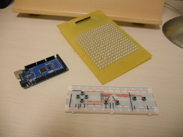
Follow these steps to build a 16 x 16 LED array with a wall (different colored LED on the border), powered by an Arduino Mega 2560. I have also included the construction details of a game controller.
This project is ideal for a beginner, as it introduces you to several fundamental elements in practical electronics. You can learn how to read data sheets, how to solder, how to work with LEDs, multiplex to save output lines, program a microcontroller through an Arduino, how to take practical factors into account in design, resistances and analog considerations in digital circuits, etc..
At the end of the project, you should be well equipped to move on to more complex ones such as LED cubes or rotating displays.
Step 1: Multiplexing Basics
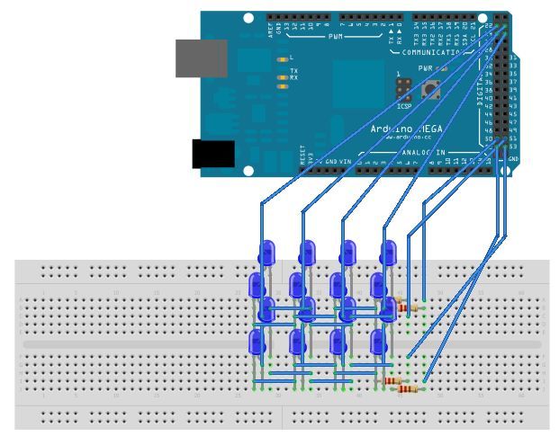
In order to have an LED Matrix of any significant size, you’ll need to control more LEDs than you have outputs. You can multiplex your LEDs to accomplish this. It works like this:
The LEDs are arranged in a rectangle. The anodes are soldered together in one direction and the cathodes are soldered together perpendicular to the anodes. When all cathodes are high and anodes are low a negative voltage is applied to every LED, and if the voltage is low enough (see ‘choosing LEDs’ in components section), it will not breakdown. To turn on a particular LED, turn its cathode line low and anode line high. For example, to turn on LED (4,2) in the diagram, you would set segB to high and Dig4 to low.
The setup uses POV (Persistence of Vision) to draw an image on the array. Each LED required to draw the image is turned on one at a time, and looped very fast, giving the illusion that all LEDs are on at the same time (see programming section).
In this project, I used the Arduino Mega 2560, and assigned 16 outputs to cathodes and 16 to anodes. I used the HIGH voltage output (5V) as the power source. This was done for simplicity in a first project. However, if you can, you should avoid using a digital signal as a power source. There are a few reasons for this. Digital outputs are signals, and aren’t designed to provide much current. You can breach the per-line or overall current limit of your microcontroller (40mA per line supply/sink for the Atmega) if your circuit draws much power. Also, the digital outputs in the Arduino and virtually every board are directly wired to the microcontroller without a fuse. This makes the microcontroller vulnerable to errors in your wiring. A simple short circuit, for example, can potentially render the pins or the microcontroller useless. However, the main fuse that limits overall current draw should prevent this.
The Ideal solution is to use the digital outputs to turn on/off a transistor at each line, and use an external power supply to drive the circuit. This increases wiring complexity, and of course, you need an external power supply for this. If you are building this as practice before you build more complex projects like a cube, you should consider going the transistor route. If you are doing this as a small project, your LED array won’t be too large, or you’re constrained on time / cost, then you can skip using transistors.
If you are using an external power supply, you can also consider using shift registers and the function shift_out to increase the number of your output pins. This increases wiring and programming complexity, although it is almost impossible to construct projects that needs the controlling of large numbers of LEDs, like a cube, without it.
Step 2: Components
To build the array and the controller, I used these parts.
– An Arduino Mega 2560
– LEDs (256)
– Resistors (16)
– Prototyping board
– Push buttons (8)
– Breadboard
– IDE / ribbon cables (2)
– Interconnects
– Wires and wirecutter
– Soldering iron and solder
– Insulating tape
– I chose the Arduino Mega because I wanted to build a 16 x 16 matrix, and needed 32 outputs for this. You can use the Arduino Uno (14 I/O pins), but you will be limited to a 7×7 matrix and no space for a controller.
– For an n x n matrix, the number of LEDs required increase as a function of n^2. So the larger you go, the number of LEDs, and your soldering time increases exponentially. Take this into consideration.
– Look for volume discounts (price breaks). The LEDs I used were 365-1189-ND and 365-1190-ND from digikey, using the 100 and 250 price breaks.
– The best place to buy LEDs from however, is ebay. You don’t need very high quality components for such projects, and you can easily get 1000 LEDs for around $30 from ebay, if you can wait for shipping from China.
– IDE cables have a missing pin in the middle. But almost all electronics stores have ribbon cables in the old format, without the missing pin.
When choosing your LEDs, consider a few things:
– As the LED array is meant to be viewed from the front only, you don’t need LEDs that have a large viewing angle.
– They should function within your input voltage range and current.
– They should have a high enough MCD rating so that they are bright enough at a very low duty cycle (1 / no. of LEDs).
– You should ensure that the LEDs can withstand a negative power voltage (check I-V curve in datasheet).
– LEDs (256)
– Resistors (16)
– Prototyping board
– Push buttons (8)
– Breadboard
– IDE / ribbon cables (2)
– Interconnects
– Wires and wirecutter
– Soldering iron and solder
– Insulating tape
For more detail: LED Matrix with Game Controller using an Arduino