
Summary of Waveform Generator using an Arduino
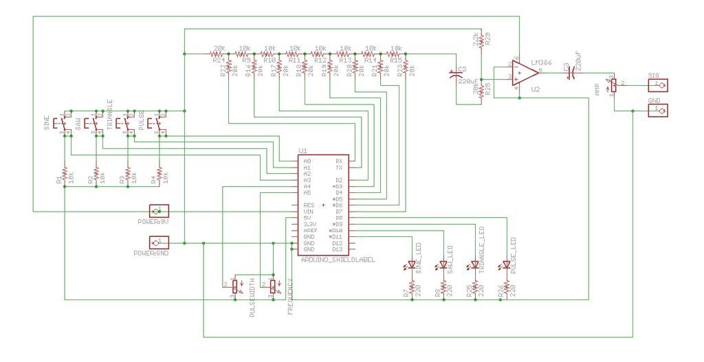
This Arduino-powered waveform generator outputs sine, triangle, pulse, and saw waves from 1 Hz to 50 kHz, with frequency, pulse width, and amplitude controlled by three potentiometers. Optional indicator LEDs show the active waveform. The project uses an Arduino Uno with a proto shield, an LM386 amplifier for audio output, pushbuttons to select waveforms, and a custom enclosure with an audio jack.
Parts used in the Waveform Generator:
- Mini SPST 1.5-Amp Momentary Pushbutton Switch (4x)
- 10K Ohm 1/4-Watt Carbon Film Resistor (8x)
- 20K Ohm 1/4-Watt Carbon Film Resistor (9x)
- 50K-Ohm Linear-Taper Potentiometer (1x)
- 10K-Ohm Audio-Taper Potentiometer (1x)
- 10K-Ohm Audio Control Potentiometer with SPST Switch (1x)
- 1/8 Inch Stereo In-Line Audio Jack (1x)
- 10.01 µF 50V Ceramic Disc Capacitor (1x)
- 4.7K Ohm 1/4-Watt Carbon Film Resistor (1x)
- 8 Pin Socket (1x)
- LM386 Low Voltage Audio Power Amplifier (1x)
- 220 µF 35V Radial-lead Electrolytic Capacitor (2x)
- Arduino Uno REV 3 (1x)
- Arduino Proto Shield (1x)
- White Super-bright LED Indicator (4x)
- 740 ohm 1/4W 5% Carbon Film Resistor (4x)
- 300 Ohm resistor (1x)
Waveform generators (also called function generators) are useful for testing and debugging circuits. I often use them to test the frequency response of electronics components like op amp and sensors. This waveform generator is powered by an Arduino. It outputs four waveshapes: sine, triangle, pulse, and saw, each waveshape ranges in frequency from 1Hz-50kHz. The frequency, pulse width, and overall amplitude (gain) of the waveforms is controlled by three potentiometers. I’ve also included (optional) indicator LEDs that let you know which type of wave is currently being sent to the output.
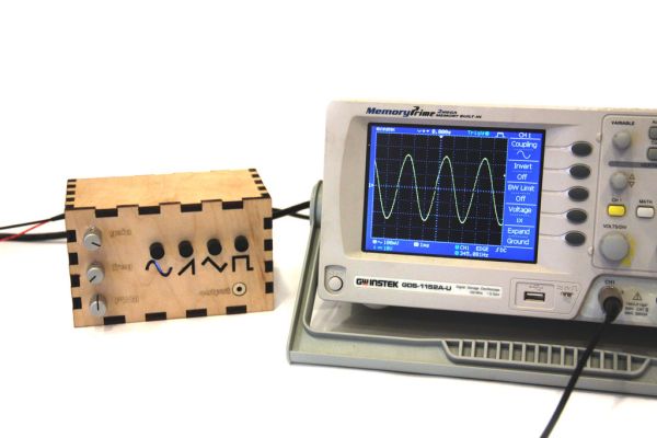
Parts List:
(4x) Mini SPST 1.5-Amp Momentary Pushbutton Switch (2 packages) Radioshack #275-1556
(8x) 10K Ohm 1/4-Watt Carbon Film Resistor (2 packages) Radioshack #271-1335
(9x) 20K Ohm 1/4-Watt Carbon Film Resistor (2 packages)
(1x) 50K-Ohm Linear-Taper Potentiometer Radioshack #271-1716
(1x) 10K-Omh Audio-Taper Potentiometer Radioshack #271-1721
(1x) 10K-Ohm Audio Control Potentiometer with SPST Switch Radioshack #271-215
(1x) 1/8″ Stereo In-Line Audio Jack Radioshack #274-274
(1x) 10.01µf 50V Ceramic Disc Capacitor Radioshack #55047551
(1x) 4.7K Ohm 1/4-Watt Carbon Film Resistor Radioshack #271-1330
(1x) 8 Pin Socket Radioshack #276-1995
(1x) LM386 Low Voltage Audio Power Amplifier Radioshack #276-1731
(2x) 220µF 35V 20% Radial-lead Electrolytic Capacitor (or anything between 200 and 300 uF) Radioshack #272-1029
(1x) Arduino Uno REV 3 Radioshack #276-128
(1x) Arduino Proto Shield Radioshack #276-140
(4x) White Super-bright LED Indicator Radioshack #55050633
(4x) 740 ohm 1/4W 5% Carbon Film Resistor (1 package) Radioshack 271-1317
(1x) 300Ohm resistor
Additional Materials:
Heat Shrink Radioshack #278-1611
22 Gauge Wire Radioshack #278-1224
Solder Radioshack #64-013
Drill
Hot Glue
Glue
Black diffusor material (tissue paper, plastic, etc)
Step 1: Prepare Arduino Proto Shield
The Arduino Proto Shields are a convenient way to attach circuits to an Arduino, but I like to trim them down a little bit first so they do not take up so much room in the project enclosure. Start by trimming the pins down with a pair of wire cutters. Next, cut off the six pin socket. Finally, cut the sockets from the top of the board.
Step 2: Enclosure
(3x) 7mm holes for gain, freq, and PWM pots
(3x) 7mm holes for four push buttons- sin, saw, tri, and pulse
(1x) 10mm hole for audio out
I cut out shapes of all four waveforms in the front of the enclosure so that I could backlight them with indicator LEDs, you may choose to just drill four 5mm holes for these LEDs in the front panel of the enclosure, place one LED under each momentary switch.
Also include a rectangular (11mm tall, 12mm wide) cutout somewhere on the side of the enclosure for the arduino’s usb port.
I made my project enclosure out of wood, so I had to glue all the pieces (except the bottom) together with wood glue. I will attach the bottom panel on later in this instructable.
 enclosure.stl1 KB
 function generator enclosure.cdr
 enclosure.dwg228 KB
Step 3: Solder Button Leads
Solder a 10kOhm resistor to one lead of each of the four push buttons. As shown in the second image, solder a green wire to the junction between the button and the resistor and a red wire to the other end of the resistor. Solder a black wire the the second lead of the push button. It’s a good idea to cover these connections with a bit of heat shrink to prevent short circuits (fig 2).
Step 4: Install Audio Jack
Unscrew the plastic casing from the audio jack. Solder a red wire to the two stereo out pins and solder a black wire to the ground pin (fig 3). I used hot glue to prevent short circuiting the jack and to give the soldering joints some extra support. Finally, mount the audio jack in the enclosure with super glue.
(8x) 10K Ohm 1/4-Watt Carbon Film Resistor (2 packages) Radioshack #271-1335
(9x) 20K Ohm 1/4-Watt Carbon Film Resistor (2 packages)
(1x) 50K-Ohm Linear-Taper Potentiometer Radioshack #271-1716
(1x) 10K-Omh Audio-Taper Potentiometer Radioshack #271-1721
(1x) 10K-Ohm Audio Control Potentiometer with SPST Switch Radioshack #271-215
(1x) 1/8″ Stereo In-Line Audio Jack Radioshack #274-274
(1x) 10.01µf 50V Ceramic Disc Capacitor Radioshack #55047551
(1x) 4.7K Ohm 1/4-Watt Carbon Film Resistor Radioshack #271-1330
(1x) 8 Pin Socket Radioshack #276-1995
(1x) LM386 Low Voltage Audio Power Amplifier Radioshack #276-1731
(2x) 220µF 35V 20% Radial-lead Electrolytic Capacitor (or anything between 200 and 300 uF) Radioshack #272-1029
(1x) Arduino Uno REV 3 Radioshack #276-128
(1x) Arduino Proto Shield Radioshack #276-140
(4x) White Super-bright LED Indicator Radioshack #55050633
(4x) 740 ohm 1/4W 5% Carbon Film Resistor (1 package) Radioshack 271-1317
(1x) 300Ohm resistor
For more detail: Waveform Generator using an Arduino
- What waveforms does the generator produce?
It outputs sine, triangle, pulse, and saw waveforms. - What frequency range does the generator cover?
The waveforms range from 1 Hz to 50 kHz. - How are frequency, pulse width, and amplitude adjusted?
They are controlled by three potentiometers for frequency, PWM (pulse width), and overall gain. - Does the project include indicators for the active waveform?
Yes, optional indicator LEDs can backlight waveform symbols or be placed under each momentary switch. - What microcontroller is used to generate the waveforms?
An Arduino Uno REV 3 is used with an Arduino Proto Shield. - How is the audio output implemented?
The audio output uses an LM386 audio power amplifier and a 1/8 inch stereo audio jack. - Are there instructions for the enclosure?
Yes, laser-cut 2D and 3D files (AI, CDR, DWG, STL) are provided; holes to drill are specified if not using a laser cutter. - How are the pushbuttons wired for the selector switches?
Solder a 10K resistor to one lead of each pushbutton, connect a green wire to the junction, a red wire to the resistor end, and a black wire to the other lead; cover with heat shrink. - What extra materials are recommended for assembly?
Heat shrink, 22 gauge wire, solder, drill, hot glue, regular glue, and diffuser material for LEDs are recommended.
