In this project, we will use the digital pins and screen of the 4Duino to create a 5×7 LED matrix controller with a user graphical interface.
An LED matrix is essentially many LEDs packaged in a dot grid format in order to produce pictures or large text. They’re commonly used for signage purposes in the public space. The LED matrix utilised in this project is made by multiplexing 35 LEDs together such that there are 5 columns and 7 rows to control the matrix. In this set up, we have row anodes and column cathodes. To light up a particular LED in our example matrix, the row pins are switched to HIGH voltage state and column pins are switched to LOW.
Step 1: How It Works
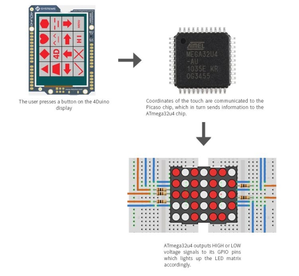
When a user presses any shape button on the 4Duino display, coordinates of the touch are communicated to the Picaso chip, which in turns sends information to the ATMega32U4 chip. ATMega32U4 outputs HIGH or LOW voltage signals to its GPIO pin which lights up the LED matrix accordingly.
Step 2: BUILD
Collect the following materials:
- 4Duino
- Kingbright 50mm (2.0 INCH) 5×7 DOT MATRIX DISPLAY (TA20-11SRWA)
- Jumper Cables
- Breadboard
- 5x resistors (between 100 – 300 Ω)
- Micro USB cable
- µSD card
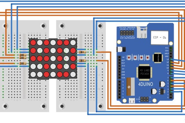
Connect these as shown in the diagram above.
For more details on the pin layout of the LED matrix, please refer to the TA20-11SRWAdatasheet. Note that the original datasheet have column cathodes and row anodes – the LED matrix used in this example have column anodes and row cathodes, but the pin connections for the 4Duino will still be the same regardless of the direction of the rows and columns. All that really needs changing is the digitalWrite() commands in the 4Duino code for rows and columns.
If your LED matrix is column anode and row cathode, replace all the “HIGH” words in this code section to “LOW” and “LOW” to “HIGH”. If your LED matrix is column cathode and row anode, you are not required to modify this code.
Step 3: PROGRAM
Workshop 4 – 4Duino Extended Graphics environment is used to program this project.
This project requires the Arduino IDE to be installed as Workshop calls the Arduino IDE for compiling the Arduino sketches. The Arduino IDE however is not required to be opened or modified to program the 4Duino.
- Download the project here. Open this file using Workshop 4.
- Connect the 4Duino to the PC using µUSB cable.
- Then navigate to the Comms tab and select the Comms port to which the 4Duino connected.
- Finally, go back to “Home” tab and now click on the “Comp’nLoad” button.
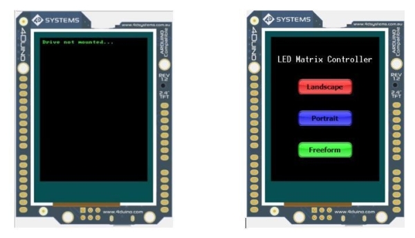
- The Workshop 4 IDE will prompt you to insert a µSD card to the PC in order to save the widget images. Insert µSD card, select the appropriate drive and press button “OK”. If the µSD card already have the widget images, you can choose to click on “No Thanks”.
Step 4: DEMO
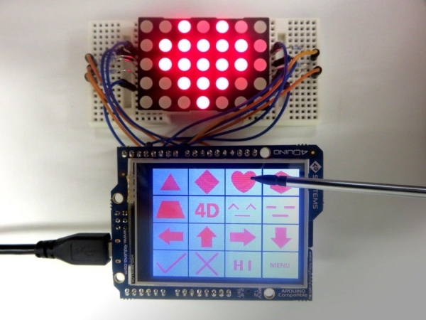
Experiment around with the controller – there are several options of matrix control modes to choose from.
Go to 4Duino Projects for more creative stuff
Source: LED Matrix Controller Using 4Duino