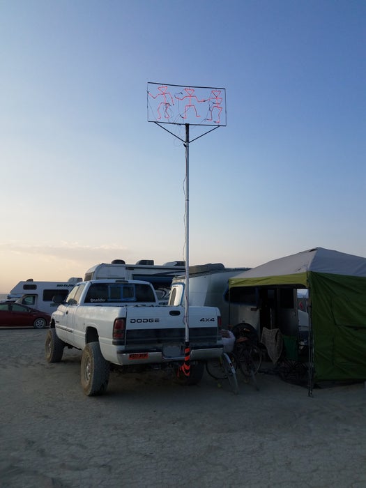
I wanted to make something so I could find our camp at night at Burning Man 2018. 2018 was a robot theme and I’m a fan of neon but no way was gonna head that route so I came up with an idea about a dancing cocktail glass kinda robot.
We beach camp and have sand rails so I know how useful flying some kind of flag can be during the day and some kind of LED light pole is at night. So I figured, use it an burning man and keep using when we go to the beach.
So using metal and welding is in my wheel house and I’m good with Arduinos so that’s the medium that I chose to implement this project in.
This instructable is pretty brief but any questions feel free to ask!
Step 1: Design

From using a flag pole on the trailer hitch of my truck I know how flimsy these things are. Thin wall aluminum tubing for the flag pole can fly two 3X6-ish flags on a normal day. In heavy wind conditions it can put the hurt on the pole.
Because my project was gonna be on the top of a 20 ft flag pole I knew I had to keep it as light as possible but also sturdy enough that it can be stored and travel to and from where its going in the back of a truck.
I also knew it couldn’t be like 10ft tall because it would end up breaking/folding over the flag pole.
So I made a executive decision to make each dude 2 feet tall. Ideally I wanted to stack them one in front of the other but anticipating the wiring mess that was to follow I knew that wouldn’t work so three bots next to each other was the way to go.
I drew a stick figure out, worked out proportions for arms & legs and came up with a stick model. From there I worked out three different moves.
Design done!
Step 2: Implementation of the Frame & Dudes

I wanted to keep it light so for the dude frames so I went with 1/8″ steel rod/wire. Inexpensive, bendable, braze-able, weldable, available.
I bent the bodies in a vice, bent the shoulders/arms & bent the basic legs.
To connect them I brazed them together (I like brazing) Also welding – very low heat.
Then using my printed out images, bent them into shape.
Laid them on the ground, and figured what I needed for a frame – size wise
Chose 1/2 X 1/8 flat steel for the frame. Used two pieces, 4 ninety degree bends and welded up the frame.
Welded top and bottom rods to attach the dudes into the frame.
BTW, neatness didn’t count here. I was under a hard time crunch (leaving for the event) and of course it’s 20 ft up on a flag pole so no one can see it close up anyway.
I added a tube on the bottom that would go over the existing flag pole and two additional supports because it was flex-ly as heck. I couldn’t easily address the forward/backward motion easily but the side to side bu adding the two additional struts that attach to the flag pole mount that address that problem.
Even with this – the thing was flimsy as heck. But it also doesn’t have a lot of surface area so I was hoping winds wouldn’t affect it much.
Step 3: Parts Used

Pretty basic stuff. LEDs, arduino, relay board lots and lots of zip ties and shrink tubing.
Also, wire and connectors. I’m not going to include a picture of the connectors because I was majorly dis-satisfied with how awkward and tedious there were to use.
Step 4: Arduino Code & Control Box

Again very basic stuff here. I needed to turn on each of the dudes, switching between them.
For assembly I DID NOT screw the wires into the relays. I’ve had tremendous trouble in the past doing this. The screws on the relay board somehow relax and the wires fall out. I ended up soldering the wires from the Arduino directly to the pads on the PC board.
Once it was wired and in the box, I hot glued the wires to both the relay board and the Arduino. I didn’t want to have a wire slip off and have to trouble shoot it in the dark when it wasn’t working.
I laser cut a piece of fiber board to attach the Arduino and the relay board to, then attached the fiber board to the aluminum box. I did this – first because I could 🙂 and second, I wanted to work out all of the wires and spacing on the fiber board before I put it in the aluminum box which is tough to try to do anything once it’s in there.
I didn’t worry much about grommets or anything. It was gonna get dusty but It was sitting in the back of the truck.
POWER –
The LEDs want 12 volts. The Arduino will run on 12v but it cannot source the LEDs. That’s why I have the relay board.
Also I ran this from a 12v car battery so I had plenty of hours run time before I had to worry about recharging.
Step 5: Attaching the LED Strips to the Dancing Dudes
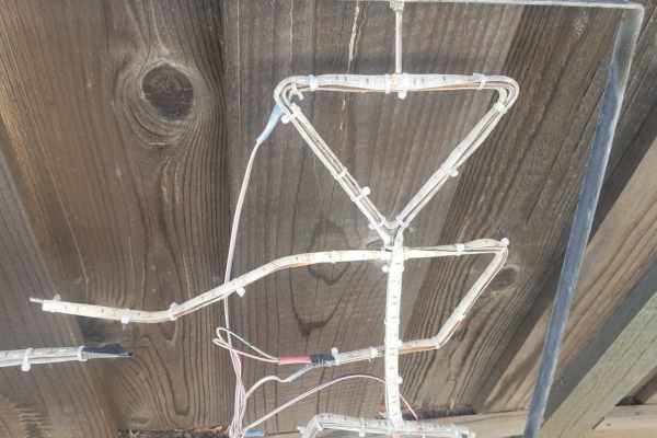
This was by far the hardest and most tedious part.
The LEDs are the waterproof ones. They have a clear rubber coating on them
First I tried to attach the LEDs to one side of the dude. Night test show me that I could only see the LEDs from one side – duh… I only tried this with part of one dude..
So – I tried to attach LEDs to the inside and outside and front and back. Turns out the lights are bright enough you cannot tell one from the other when its up on the pole – let along a block away.
So the LEDs are sticky on the back side – USELESS for this project. It wouldn’t stick to the 1/8″ rod. So tie wrap time! Lots and lots and lots of tie wraps!
Also if you bend the LED strips too much – they break – then you have to toss the part of the LED strip and start again…
I tried to be tricky and make one strip cover as much of a dude as possible. It kinda worked. I ended up having multiple strips connected together.
NOTE –
For these LED strips lots of people sell no-solder clip on connectors – connectors that basically give you two wires on the end of a strip to connect a battery to. THESE DO NOT WORK very well with the water proof strips. For the water proof strips you have to cut away the rubber coating to expose the copper leads on the flexy LED strip. I trashed quite a few before I worked up a technique on how to strip back the rubber. Even then the no solder clamp on connectors would take any kind of pulling on them and they had to fit exactly so they would land on the tabs. JUNK IMHO. So I ended up soldering the wires to the LED strips and shrink wrapping the connection. This is the connection you’ll see when you open up a new box. Soldered on….
Every connection was heat shrink-ed and multiple connections were heat shrik-ed again. It was gonna be out in the elements so this will hopefully help keep the connections out of the elements.
Source: LED Dancing Robots