Summary of LCD interfacing with arduino
This tutorial explains connecting a 16x2 parallel LCD to an Arduino using a 4-bit interface to minimize I/O pin usage. It details the necessary hardware, including a specific resistor for contrast adjustment, and provides a step-by-step guide on wiring ten pins from the LCD to the microcontroller while keeping the Read/Write pin grounded for write-only operations.
Parts used in the 16x2 LCD with Arduino Project:
- 16x2 LCD
- Arduino Board
- Connecting wires
- 1K Ohm Resistor
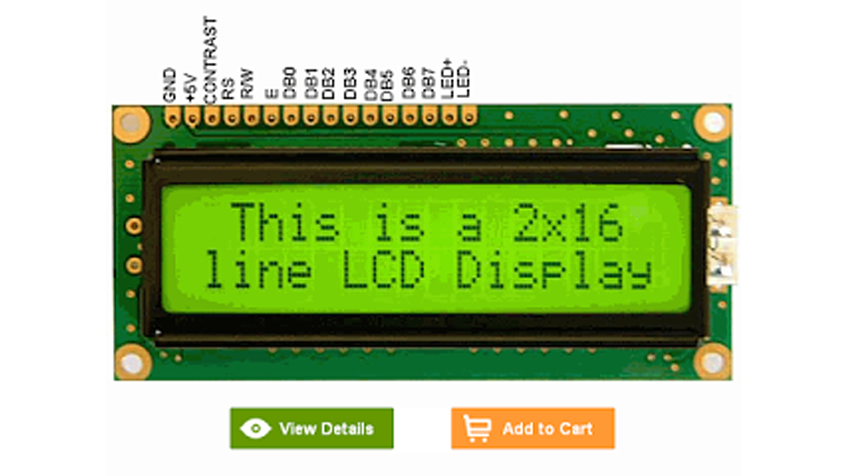
In this tutorial we’ll be looking at how to connect interface parallel LCD to an Arduino. We are using 16 char x 2 Line LCD known as 16×2 LCD, you can usually identify this display by the 16-pin interface. You only need to solder 10 of the 16 wires to use the LCD, but this will only enable you to use the 4-bit interface. 4-Bit interface helps us to reduce required IO lines, there are various displays available such as 16×2, 16×4, 20×2, 20×4 LCD Display.
Step 1: Components Required
- 16×2 LCD
- Arduino Board
- Connecting wires
- 1K Ohm Resistor
Step 2: Circuit diagram/connections
- Most of the time we don’t need to read the display so we always write on the display. Pin 5 RD/WR when it is connected to logic 0, It is write operation, to reduce IO requirement we connect it to GND (Logic 0 Always Write)
- Contrast setting, LCD contrast can be adjusted by setting proper voltage at Pin 3. Connecting variable resistor takes lot of space and possibility of setting wrong contrast value due to change in resistance with change in atmospheric condition. I use 1KOhm resistor between GND and Pin 3. It gives perfect contrast setting.
As I mentioned before, you only need to connect 10 pins. Solder jumpers to these wires:
Pin 1 – Ground
Pin 2 – +5V
Pin 3 – Contrast Adjustment (1K Ohm resistor to GND)
Pin 4 – Register Select
Pin 5 – Read/Write (Connect to GND)
Pin 6 – H/L Enable
Pin 11 – DB4
Pin 12 – DB5
Pin 13 – DB6
Pin 14 – DB7
As shown in the picture below:
Pin 1 to GND
Pin 2 to 5V
Pin 3 to (1K Ohm resistor to GND)
Pin 4 to Arduino pin 12
Pin 5 to GND
Pin 6 to Arduino pin 11
Pin 11 to Arduino pin 5
Pin 12 to pin 4
Pin 13 to pin 3
Pin 14 to pin 2
Read More: LCD interfacing with arduino
- How many wires need to be soldered to use the LCD?
You only need to solder 10 of the 16 wires. - What is the purpose of the 4-bit interface?
The 4-bit interface helps reduce the required IO lines. - Why is Pin 5 connected to GND?
Pin 5 is connected to GND (Logic 0) to ensure it is always in write operation mode. - What component is used for contrast setting instead of a variable resistor?
A 1K Ohm resistor between GND and Pin 3 is used to give perfect contrast setting. - Which Arduino pin connects to LCD Pin 4?
LCD Pin 4 connects to Arduino pin 12. - Can this project support displays other than 16x2?
Yes, various displays such as 16x4, 20x2, and 20x4 are available. - What happens if you connect Pin 5 to logic 0?
It becomes a write operation.