Summary of LC Meter using Arduino: Measuring Inductance and Frequency
This project builds an Arduino-based LC meter that measures and displays inductance, capacitance, and resonance frequency on a 16x2 LCD. A 741 op-amp converts the LC circuit's sinusoidal oscillation into a square wave, which the Arduino times via pulseIn to compute frequency; formulas then derive L or C. A push button toggles measurement mode; presets require C=0.1µF when measuring L and L=10mH when measuring C.
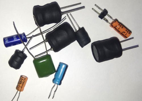
Parts used in the LC Meter:
- Arduino Uno
- 741 opamp IC
- 3v battery
- 100-ohm resistor
- Capacitors (including 0.1uF)
- Inductors (including 10mH)
- 1n4007 diode
- 10k resistor
- 10k potentiometer
- Power supply (USB or 12v adaptor for Arduino)
- Push button
- 16x2 LCD
- Breadboard or PCB
- Connecting wires

All embedded lovers are familiar with multimeter which a great tool to measure voltage, current, resistance etc. A multimeter can measure them easily. But sometimes we need to measure inductance and capacitance which is not possible with a normal multimeter. There are some special multimeters that can measure inductance and capacitance but they are costly. We already built Frequency Meter, Capacitance Meter and Resistance meter using Arduino. So today we are going to make an Inductance LC Meter using Arduino. In this project, we will show the inductance and capacitance values along with the frequency over 16×2 LCD display. A push button is given in the circuit, to switch between capacitance and inductance display.
Components Required
- Arduino Uno
- 741 opamp IC
- 3v battery
- 100-ohm resistor
- Capacitors
- Inductors
- 1n4007 diode
- 10k resistor
- 10k pot
- Power supply
- Push button
- Breadboard or PCB
- Connecting wires
Calculating Frequency and Inductance
In this project we are going to measure inductance and capacitance by using an LC circuit in parallel. This circuit is a like a ring or bell which start resonating at certain frequency. Whenever we apply a pulse, this LC circuit will start resonating and this resonance frequency is in form of analog (sinusoidal wave) so we need to convert it in squire wave. To do this, we apply this analog resonance frequency to opamp (741 in our case) that will convert it in squire wave (frequency) at 50% of the duty cycle. Now we measure the frequency by using Arduino and by using some mathematical calculation we can find the inductance or capacitance. We have used the given LC circuit frequency response formula.
f=1/(2*time)
where time is output of pulseIn() function
now we have LC circuit Frequency:
f=1/2*Pi* square root of (LC)
we can solve it to get inductance:
f2 = 1/ (4Pi2LC)
L= 1/ (4Pi2 f2C)
L = 1/(4* Pi * Pi * f * f * C)
As we already mentioned that our wave is sinusoidal wave so it has the same time period in both positive and negative amplitude. Its means the comparator will convert it into square wave having a 50% duty cycle. So that we can measure it by using pulseIn() function of Arduino. This function will give us a time period which can be easily converted into a frequency by inverting the time period. As pulseIn function measure only one pulse, so now to get correct frequency we have to multiply it by to 2. Now we have a frequency which can be converted into inductance by using the above formula.
Note: while measuring inductance (L1), capacitor (C1) value should be 0.1uF and while measuring capacitance (C1), inductor (L1) value should be 10mH.
Circuit Diagram and Explanation
In this LC Meter circuit diagram, we have used Arduino to control the project operation. In this, we have used an LC circuit. This LC circuit consists of an Inductor and a capacitor. To convert sinusoidal resonance frequency to digital or square wave we have used operational amplifier namely 741. Here we need to apply negative supply to op-amp to get accurate output frequency. So we have used a 3v battery connected in reverse polarity, means 741 negative pin is connected to battery negative terminal and positive pin of the battery is connected to the ground of the remaining circuit. For more clarification see the circuit diagram below.
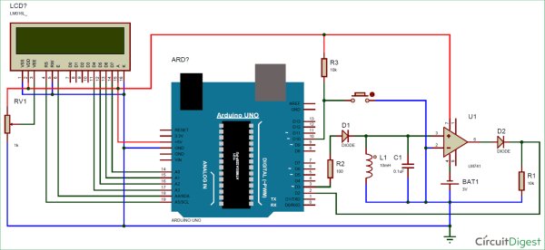
Here we have a push button to change the mode of operation whether we are measuring inductance or capacitance. A 16×2 LCD is used to show inductance or capacitance with the frequency of LC circuit. A 10k pot is used for controlling the brightness of the LCD. Circuit is powered with the help of Arduino 5v supply and we can power the Arduino by 5v using USB or 12v adaptor.

Measuring Frequency and Capacitance
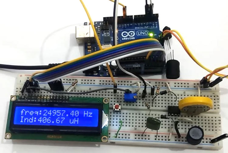
Measuring Frequency and Inductance
Programming Explanation
The programming part of this LC Meter project is very easy. Complete Arduino code is given at the end of this article.
First we have to include library for LCD and declare some pins and macros.
#include<LiquidCrystal.h>
LiquidCrystal lcd(A5, A4, A3, A2, A1, A0);
#define serial
#define charge 3
#define freqIn 2
#define mode 10
#define Delay 15
double frequency, capacitance, inductance;
typedef struct
{
int flag: 1;
}Flag;
Flag Bit;
After it, in setup function we have initialized LCD and Serial communication to show measured values over the LCD and serial monitor.
void setup()
{
#ifdef serial
Serial.begin(9600);
#endif
lcd.begin(16, 2);
pinMode(freqIn, INPUT);
pinMode(charge, OUTPUT);
pinMode(mode, INPUT_PULLUP);
lcd.print(” LC Meter Using “);
lcd.setCursor(0, 1);
lcd.print(” Arduino “);
delay(2000);
lcd.clear();
lcd.print(“Circuit Digest”);
delay(2000);
}
Then in loop function, apply a pulse of a fixed time period to LC circuit that will charge the LC circuit. After removing pulse LC circuit starts resonating. Then we read its square wave conversion, coming from op-amp, by using pulseIn()function and convert that by multiplying by 2. Here we have taken some samples of this too. That’s how frequency is calculated:
void loop()
{
for(int i=0;i<Delay;i++)
{
digitalWrite(charge, HIGH);
delayMicroseconds(100);
digitalWrite(charge, LOW);
delayMicroseconds(50);
double Pulse = pulseIn(freqIn, HIGH, 10000);
if (Pulse > 0.1)
frequency+= 1.E6 / (2 * Pulse);
delay(20);
}
frequency/=Delay;
#ifdef serial
Serial.print(“frequency:”);
Serial.print( frequency );
Serial.print(” Hz “);
#endif
lcd.setCursor(0, 0);
lcd.print(“freq:”);
lcd.print( frequency );
lcd.print(” Hz “);
After getting frequency value, we have converted them into inductance by using given piece of code
capacitance = 0.1E-6;
inductance = (1. / (capacitance * frequency * frequency * 4.*3.14159 * 3.14159)) * 1.E6;
#ifdef serial
Serial.print(“Ind:”);
if(inductance>=1000)
{
Serial.print( inductance/1000 );
Serial.println(” mH”);
}
else
{
Serial.print( inductance );
Serial.println(” uH”);
}
#endif
lcd.setCursor(0, 1);
lcd.print(“Ind:”);
if(inductance>=1000)
{
lcd.print( inductance/1000 );
lcd.print(” mH “);
}
else
{
lcd.print( inductance );
lcd.print(” uH “);
}
}
And by using given code we calculated capacitance.
if (Bit.flag)
{
inductance = 1.E-3;
capacitance = ((1. / (inductance * frequency * frequency * 4.*3.14159 * 3.14159)) * 1.E9);
if((int)capacitance < 0)
capacitance=0;
#ifdef serial
Serial.print(“Capacitance:”);
Serial.print( capacitance,6);
Serial.println(” uF “);
#endif
lcd.setCursor(0, 1);
lcd.print(“Cap: “);
if(capacitance > 47)
{
lcd.print( (capacitance/1000));
lcd.print(” uF “);
}
else
{
lcd.print(capacitance);
lcd.print(” nF “);
}
}
So this is how we calculated frequency, capacitance and Inductance using Arduino and displayed it on 16×2 LCD.
Source: LC Meter using Arduino: Measuring Inductance and Frequency
- How does the project measure frequency?
The Arduino uses pulseIn on the square wave from the 741 op-amp, multiplies by 2, averages samples, and inverts the period to get frequency. - How is inductance calculated?
Inductance is computed from measured frequency using L = 1/(4 * pi^2 * f^2 * C) with C set to 0.1uF while measuring L. - How is capacitance calculated?
Capacitance is computed from measured frequency using C = 1/(4 * pi^2 * f^2 * L) with L set to 10mH while measuring C. - How is the sinusoidal LC resonance converted to a measurable signal?
A 741 op-amp acts as a comparator to convert the sinusoidal resonance into a square wave at roughly 50% duty cycle. - Can the Arduino power the circuit?
The circuit is powered by the Arduino 5V supply; the Arduino itself can be powered via USB or a 12V adapter. - What is the purpose of the push button?
The push button switches the mode between measuring inductance and measuring capacitance. - Why is a 3V battery used with the 741 op-amp?
A 3V battery is used to provide the negative supply reference for the 741 by connecting its positive to circuit ground and negative to the op-amp negative pin as described. - How are results displayed?
Measured frequency and the computed inductance or capacitance are shown on a 16x2 LCD and can also be printed to the serial monitor.