It is a truth universally acknowledged that a single cat in possession of good fortune must be in want of a laser toy. As with single gentlemen in want of future wives, some precautions must be observed. But is that not true of anything really worth having?
If you do have concerns about pets and laser safety, skip to the end of this Instructable before commenting. If you have concerns about a future wife, or even a current one, you probably need to look elsewhere.
Now, you could pop down to your local pet store and purchase a laser pointer, and perhaps even some contraption that adds rudimentary automation. You would save some money and be able to return it if it didn’t work. Or you could build something yourself. There are plenty of examples out there already, but here is my contribution to the canon. It features:
- Full smartphone control
- Manual, Auto and Scheduled Modes
- Custom application interface
- System status synced between multiple web clients
- System status mirrored on LaserKitty!! itself
- Configurable pan and tilt range restrictions
- Configurable playtime session lengths and frequencies
- Configurable play windows
- Set-up page with at-a-glance current settings
- NTP time sync
- WiFi manager for easy set-up on new networks
- Tone generator to play the Mission Impossible theme before each play session: your cat may or may not appreciate the irony.
- Pushbullet notifications to all your devices when a new playtime session starts
- Configurable Home Position so playtime ends at food bowl or stationary toy
- All settings stored in EEPROM so not lost on power outage
- And much more! Well, not really, that’s about it.
Step 1: Get Your Stuff
This is what I used:
- A mini pan and tilt assembly. This is certainly not the cheapest one you can find and it does need some modification for our purposes. I chose it because it looks a little cooler than the bargain basement plastic assemblies. As an unexpected bonus, its design allows for a very easy way to mount the laser. It comes with a couple of micro servos but I highly recommend you buy a bunch of extra ones for replacement purposes. You will need at least one extra servo (a broken one is fine).
- An enclosure. It pains me to pay $8 for a plastic box and you could definitely find something suitable for less. Something about the size of the linked enclosure is about right though.
- An ESP8266-based development board. I used the NodeMCU. It is not an overstatement to say I love these things. Easy to use within the Arduino IDE and plenty of flash memory for your web pages. Also cheap and, in my experience, very hard to fry.
- A mini laser. Ten for $6 including Amazon Prime. Are you kidding me?? Now I just have to figure out what to do with the other nine.
- A passive buzzer for the tones.
- A two channel relay. I use these for switching the servos and laser on and off. You may be able to eliminate this component as I’ll explain later.
- 5VDC power supply. Hopefully you’ll have one of these lying around from some long-forgotten gizmo but if not anything cheap and cheerful that can produce around 1A of 5VDC is what you need.
- Miscellaneous consumables such as resistors, LEDs, hook-up wire, heat shrink, solder, hot glue. The usual. I also used a barrel jack for the incoming 5VDC power supply off of my embarrassingly large collection of destroyed Arduino knock-off boards.
- Last, but by no means least, a vinyl decal for that whimsical finishing touch.
So yeah. You’re looking at about $50 all up. You could do it for less but doesn’t your kitty deserve the best?
Step 2: Tools and Resources
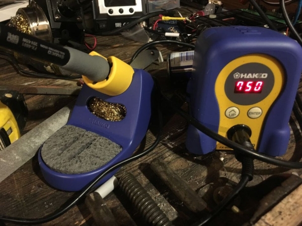
Nothing special on the tools side here. Just a decent soldering iron, multimeter, drill and basic hand tools. A bench power supply is nice for experimenting with the laser but not essential.
This project really exploits the capabilities of the ESP8266 and in particular the NodeMCU. If you are just getting started with the ESP8266, I’ve found no better one-stop resource than this thing. Other than that, it’s all about the Googling to find answers to problems that came up along the way.
Step 3: Prepare the Enclosure
As I may have already mentioned, paying $8 for a plastic enclosure seems outrageous. What’s even worse though is screwing up the thing by putting a hole in the wrong place. So before you have at your box with the drill and/or whatever other mayhem maker at your disposal, consider the mistakes I made.
- First off, you need to think about where all the stuff will fit. The good news is the enclosure I suggest has plenty of space, even with the very untidy wiring you see here. You may even be able to get away with a smaller box, especially if you eliminate the relays.
- Most important is where you will mount the pan and tilt assembly in the lid. My first attempt is shown here. I thought I’d artistically place it off center and a little ways back for stability. Bad idea! You need the assembly as close as reasonably possible to the side of the lid so the enclosure itself does not interfere with the beam at high tilt angles. Also, I think the ideal arrangement would be to mount the pan laser perpendicular to the short side rather than, as I did, the long side. I did it the other way for purely aesthetic reasons even though there is a little more potential for interference.
- As you can see, the NodeMCU is mounted on Perfboard and could easily have been positioned so that its micro USB connector was accessible from a slot in the side or rear. This would make software updates easier (no need to take off the lid). My original idea was to use the Over-The-Air (OTA) library for updates and you will see my code includes that functionality, although it is commented out. Problem was that the tone generator and OTA would not play well together (the NodeMCU would repeatedly reset halfway through the song). That issue is probably fixable but I’ve never been successful in updating SPIFFS other than via USB so having access to the USB connector would have been nice. By the time I had all this figured out I’d mounted the NodeMCU on the Perfboard in a way that meant getting the connector sticking out of the box was not possible without a lot of faffing. Oh well.
- If I were to do the project again I’d align the RGB LED with the red “power on” LED. (The purpose of the RGB LED is to indicate what mode LaserKitty!! is in without having to look at the app.)
The only slightly tricky part of actually making the holes is the rectangular one for the pan servo. I used a drill and a file. As you can see from my first attempt it is difficult to make it exactly square (or rectangular, I guess). But when the servo is mounted you can’t really see that.
You will need to make three other holes, These should be placed in the rear of the box and are used for the power supply jack, buzzer and entry point for the tilt servo and laser wiring. All these holes can be round and present no difficulty to make with just a drill.
Liberal use of hot glue secures everything in place (with the exception of the pan servo, which is bolted to the lid using the servo’s mounting tabs).
Step 4: The Pan and Tilt Assembly
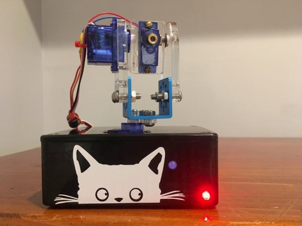
When I received the pan and tilt assembly I thought I’d made another big mistake. Put together as instructed it really isn’t a pan and tilt mechanism at all but rather a tilt and twist design – appropriate for its intended use as robot arm. However, a moment of calm reflection allowed me to see it could actually be assembled in a different way to achieve the desired result. Even better, the original location of the “twist” servo could be used as a mount for the laser.
If you examine the completed assembly in these pictures you’ll get the idea. You will be left with a small metal block that is not needed in this design.
The flash of inspiration I had was to use the original location of the second servo to mount the laser. Even better, if you decapitate a duff servo and drill out the splined arm mount it is the perfect mounting location for the laser! Just don’t underestimate the effort needed to hacksaw the servo apart. There’s some meat to those little blighters!
After assembly and installation in the enclosure, AND BEFORE APPLYING POWER, make sure it will pan pretty much 180 degrees across the face of the enclosure. Somehow or another after I’d installed it once successfully I got the pan mount put back together so that the bolt heads on the base bound up against the raised bit of the servo where the arm is intended to be mounted. Result was the servo immediately stripped its gears. On the bright side, I now have another duff servo to use as a laser mount.
Step 5: Wire It Up
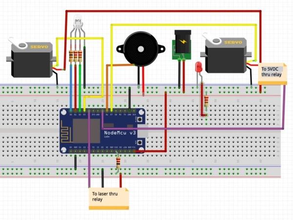
Hopefully the Fritzing sketch makes things clear. Some points to further clarify:
- As discussed later, I wanted to make the laser as dim as possible while retaining enough brightness to make it usable in all but the brightest indoor light. With a bit of experimentation I settled on powering it from a 3.3VDC pin on the Node MCU, adding a 22 Ohm resistor in series for good measure. With this set-up it draws around 10mA so in theory it could be powered directly from a GPIO pin but I found that too dim, even without the resistor.
- The laser has a a very limited ability to change focus (collimation?) which I used to make the dot bigger and thereby disperse the laser energy
- My first thought was to switch the servos on and off with a transistor but this caused the servos to go crazy. I’m sure there is a good reason for this but since I already had some relays handy I took the easy way out and totally isolated power to the servos . And since the relays had two channels I thought I might as well switch the laser that way too (the purple wires are the control signal from the MCU). I like the mechanical clicking noise this solution produces too. You may decide otherwise though. Not shown but the relays are powered directly from the 5VDC supply — the NodeMCU might just have been able to power a two channel relay directly but there was no reason to risk it. If you’ve used these relays before you’ll know this requires removing the jumper between JD-VCC and VCC.
- The RGB LED has 220 Ohm current-limiting resistors on red and green and a 100 Ohm on the blue. The red “power on” LED has a 450 Ohm resistor since it is powered from 5VDC rather than 3.3VDC. These are just ballpark values to get plenty of brightness and reasonable longevity.
- The buzzer is pretty loud. You may want to add a resistor to the signal line to attenuate the volume. The tones can be switched off completely via the software but something in between might be nice.
Step 6: The Code
Despite the rather long-winded explanation of the hardware side, 90% of the effort here went into the code. It would have been more but I “borrowed” some great code for the movement of the laser in auto mode from here. No sense reinventing the wheel. In fact, you may well decide to follow that project rather than this, or mix and match aspects of both. Certainly, I like the idea of making some of the components with a 3-D printer, but I don’t have one.
My code (found on GitHub here) is in three main parts. There is the Arduino sketch itself, HTML files with a bunch of Javascript for the application content, and associated CSS files for styling. I used this project to learn a little more about all these programming elements, starting from a very low base especially on the application interface side of things. I’ve tried to tidy up the code a bit but my main focus was on just getting the thing to work. The code uses Websockets for bidirectional communication between the NodeMCU server and connected clients.
The Arduino code is extensively commented so hopefully you’ll find it easy to follow. Once you’ve downloaded it from GitHub, stick the whole lot in a folder, upload the sketch to your MCU, then upload the contents of the “data” subfolder into SPIFFS.
Actually, scratch that. If you want to use the Pushbullet notification feature you’ll first need an API Access Token available from here. It goes in Line 88 of the Arduino code. Pushbullet works well but if you are setting up an account on your phone for the first time you might find you have to sign in, sign out, then sign in again before notifications begin to appear as configured in your phone’s settings.
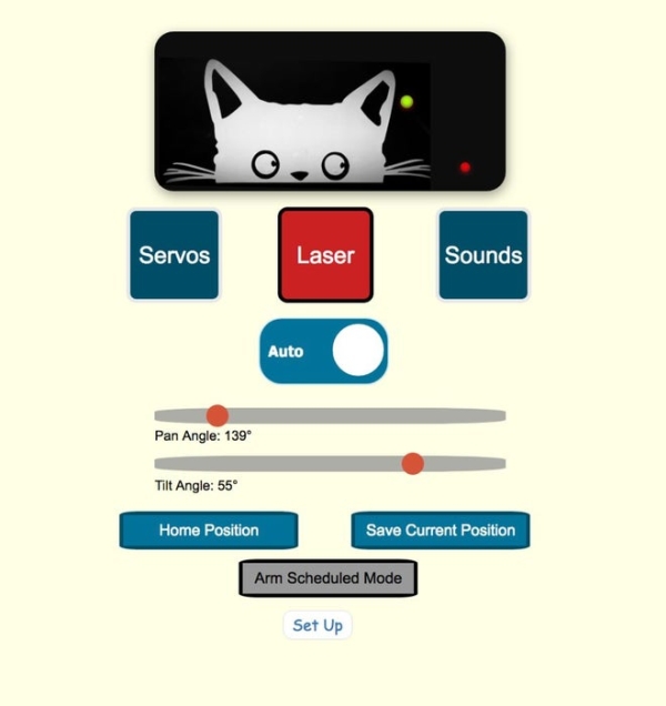
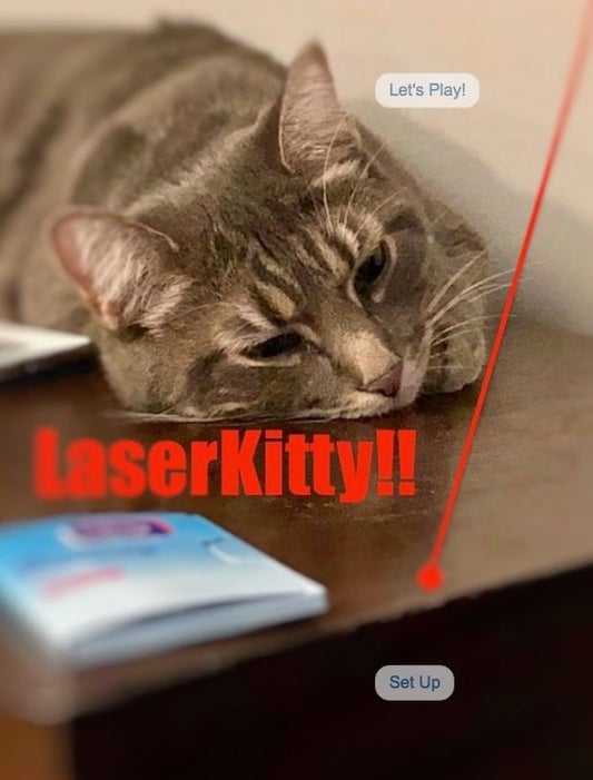
There are three web pages — a splash screen, the actual application interface, and a set-up page. Separating out the content in this way makes using the interface much more app-like, especially because of the extensive configuration options (the screenshot captures only part of these options).
One quirk of getting the NodeMCU to serve multiple pages was that I had to put all the image files in the data folder directly – just couldn’t get it to work if they were placed in subfolders. I’ve included all the images I used in the GitHub repository so it works out-of-the-box but you will doubtless wish to replace them with your own pictures.
Source: LaserKitty!!