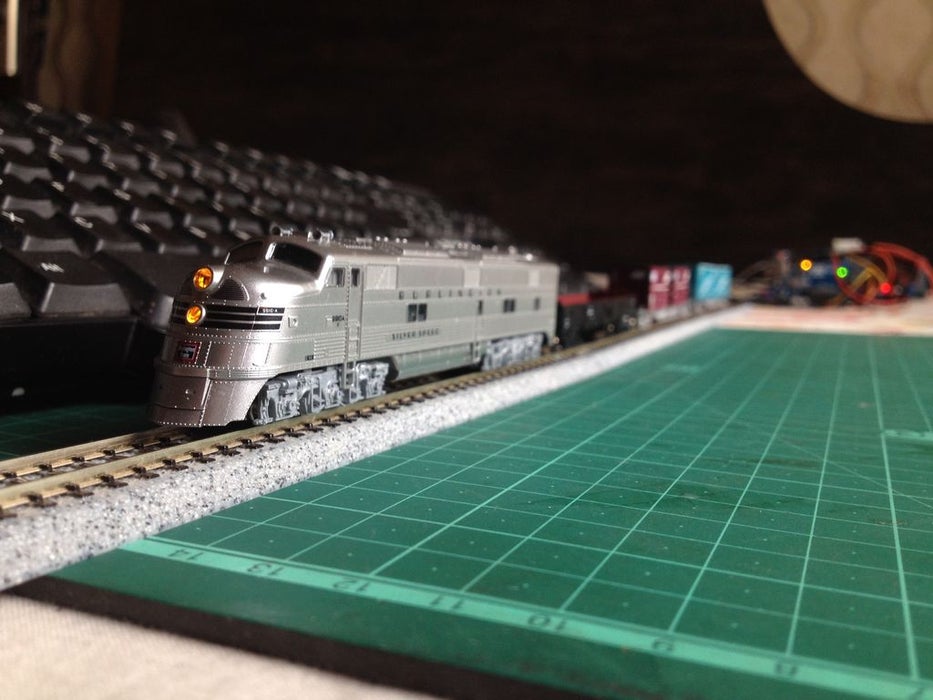
In one of my previous Instructable, I showed you how to control a model railway layout using a keyboard. It did great but had a drawback of requiring a computer to operate. In this Instructable, let’s see how to control a model train using a keyboard through Arduino. So, without further ado, let’s get started.
Step 1: Watch the Video
Step 2: Get All the Required Stuff
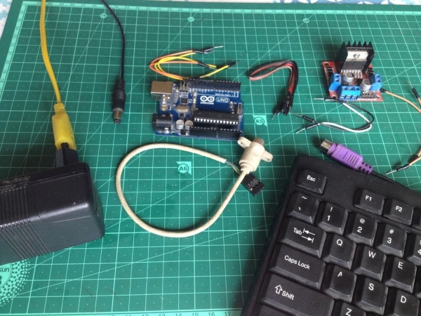
For this project you will need:
- An Arduino microcontroller
- A PS/2 keyboard
- A female PS/2 connector(Get the one as shown in the picture, it will make your life easier.)
- An L298N motor driver module
- A 12-volt DC power source with a current capacity of at least 1A(1000mA).
- 3 male to female jumper wires(To connect the motor driver’s inputs to the Arduino board’s output pins.)
- 4 male to male jumper wires(To connect the motor driver to power and the tracks.)
- 4 male to male jumper wires(To connect the PS/2 connector to the Arduino board.)
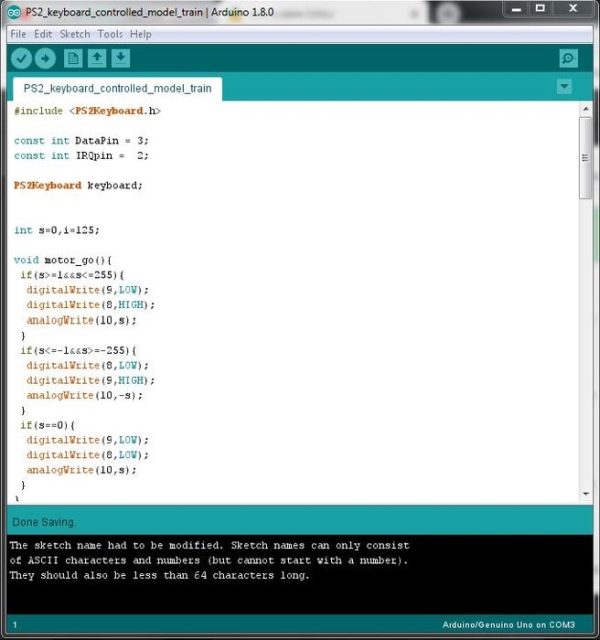
Step 3: Program the Arduino Microcontroller
Step 4: Identify the Pins of the PS/2 Connector
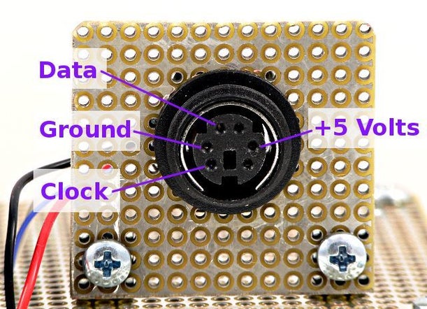
Using a multimeter set to continuity test and using the given picture as a reference, mark the pinouts of the PS/2 connector/extension cable wires.
Step 5: Connect the Motor Driver to the Arduino Board
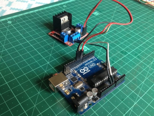
Make the following wiring connections:
- Connect the input pin ‘ENB’ to pin ‘D10’ of the Arduino board.
- Connect the input pin ‘IN4’ to pin ‘D9’ of the Arduino board.
- Connect the input pin ‘IN3’ to pin ‘D8’ of the Arduino board.
- Connect two male to male jumper wires to the output terminals 3 and 4 to be later connected to the track power feeder.
- Connect the ‘VIN’ pin of the motor driver to the ‘VIN’ pin and the ‘GND’ pin to the ‘GND’ pin of the Arduino board respectively.
Make sure no wiring connections are loose.
Step 6: Connect the PS/2 Connector to the Arduino Board
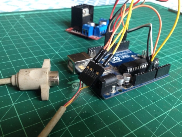
Make the following wiring connections:
- Connect ‘VCC’ to the ‘+5-volt’ pin of the Arduino board.
- Connect ‘GND’ to the ‘GND’ pin of the Arduino board.
- Connect ‘CLOCK’ to pin ‘D2’ of the Arduino board.
- Connect ‘DATA’ to pin ‘D3’ of the Arduino board.
Double check the pinout diagram of the PS/2 connector before making connections.
Source: Keyboard Controlled Model Train V2.0 | PS/2 Interface