
Summary of Isolated mains power monitoring (Arduino)
This article describes a DIY mains power monitoring circuit for Arduino, inspired by Dave Berkeley's design. The author replaced the original 10-bit ADC with a 12-bit MPC3202 due to availability issues and modified the voltage divider resistors to improve signal swing for direct line voltage measurement using opto-isolation.
Parts used in the Mains Power Monitor:
- Arduino
- MPC3202 12-bit ADC chip
- Opto-isolator (dual channel)
- 1M0 current limiting resistors
- 1M0 and 10K voltage divider resistors
- KiCAD software
All about power today.. For a while now, I’ve been looking around for a mains (220-240VAC) power monitoring circuit that I might be able to interface with an Arduino. There is of course the OpenEnergyMonitor solution, but they seem to use a transformer to isolate and measure the mains voltage. The transformer doesn’t exactly couple to the mains nicely: so the voltage on the secondary side is not a scaled voltage of the input side, the transformer itself will distort the voltage sine wave.
Then over the weekend I came across Dave Berkeley’s Project Page, and he has a cool design for mains power usage monitor that does measure the line voltage directly. HisHome Energy Monitor uses a dual channel ADC with opto-isolation, nice solution. There is loads of info over at his site, I’ve just changed a few little parts for my version. He uses a 10bit ADC [MPC2003] which I couldn’t get from RS, they were showing back order on the part, so I had a dig around and came up with a 12bit version of the same chip [MPC3202] just have to watch the conversion time, it’s not 200ksps but 100ksps, but I don’t see it being a problem (famous last words!).
So started up KiCAD and got work, then on to RS to get the parts! If you like a PDF of the circuit diagram here you go: Mains Power Monitor Circuit Diagram (rev 1.0)
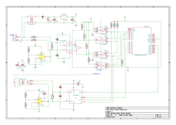
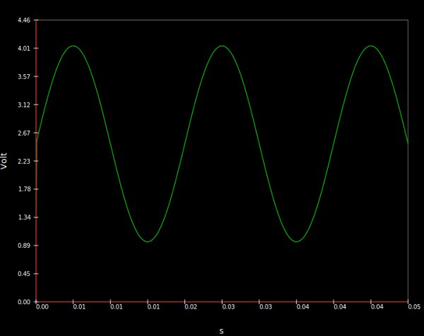
On Dave’s circuit he has a voltage divider that I couldn’t make sense of, it looks like he has 100K current limiting resisters on the two input lines and a divider made up from one of these and a 270R. The simulation on this only gave a 2.08 -> 2.92 volt swing on the ADC, given a 311V peek to peek AC input [which is 220VAC * sqt(2)]. I’ve used 1M0 on the current limiting and a divider of 1M0 and 10K, which give a little more input to the ADC.
=
For more detail: Isolated mains power monitoring (Arduino)
- Why did the author choose the MPC3202 over the MPC2003?
The author selected the MPC3202 because the MPC2003 was unavailable at RS and listed as back order. - How does this design measure mains voltage differently from OpenEnergyMonitor?
This design measures the line voltage directly rather than using a transformer that distorts the sine wave. - What modification was made to the voltage divider compared to Dave Berkeley's original circuit?
The author changed the current limiting resistors to 1M0 and the divider to a 1M0 and 10K combination. - Does the MPC3202 support the same conversion speed as the MPC2003?
No, the MPC3202 operates at 100ksps instead of the 200ksps of the MPC2003. - What tool was used to design the circuit board?
The author used KiCAD to start work on the circuit design. - What is the purpose of the opto-isolation in this project?
The opto-isolation is used to safely interface the dual channel ADC with the high voltage mains power. - What problem did the author solve regarding the original voltage divider simulation?
The author adjusted the resistor values to achieve a larger input voltage swing for the ADC.
