
Summary of IOT based Home automation and Security system
This article details an IoT-based home automation and security system built using the Arduino MKR1000. The project enables remote control of appliances like bulbs and fans while monitoring motion and gas levels via a Blynk app dashboard. It highlights the integration of sensors for intrusion detection and leak identification, utilizing the board's built-in WiFi for seamless connectivity without external modules.
Parts used in the IoT based Home Automation and Security System:
- Arduino MKR 1000
- PIR Sensor
- Gas sensor
- Relay circuit
- Bulb
- AC motor
- Diodes(1n 4007)
- Transistor
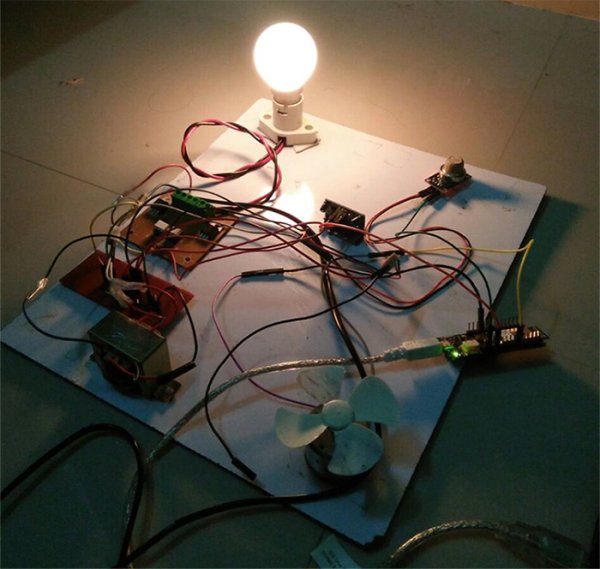
HARDWARE COMPONENTS USED:
- Arduino MKR 1000
- PIR Sensor
- Gas sensor
- Relay circuit
- Bulb
- AC motor
- Diodes(1n 4007)
SOFTWARE USED:
- Blynk App (Android/ iOS)
BLYNK APPLICATION:
Blynk is an IOT software platform which is available for both android and iOS. This platform is very much like a digital dashboard in which you can see all information from your connected devices. And the most of all Blynk supports many famous development boards like Raspberry Pi, Arduino, ESP8266 and other IOT platforms .
In our project this platform is used for following purposes
- Turn ON/OFF bulb and fan.
- Readings can be viewed from PIR and Gas sensor values.
- Monitoring of sensor values are made possible
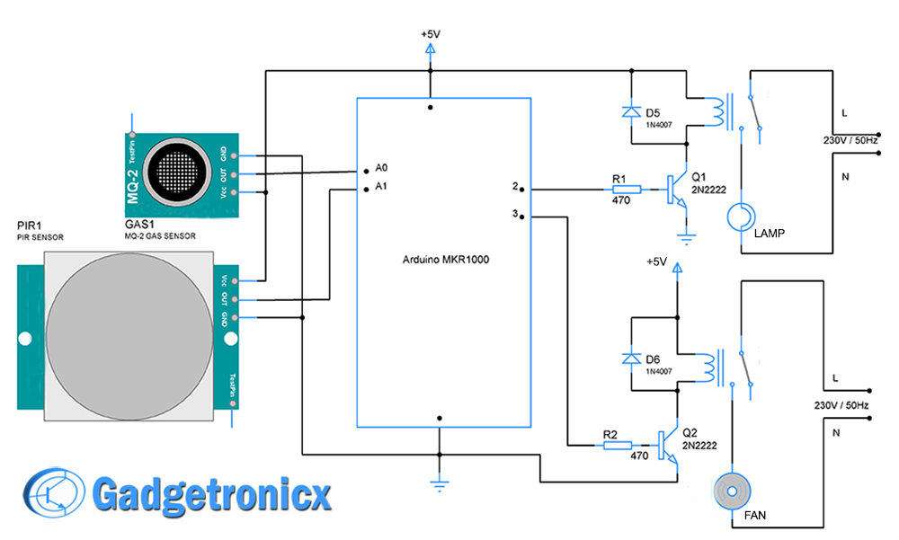
SCHEMATIC DIAGRAM OF HOME AUTOMATION SYSTEM:
EXPLANATION:
In this schematic PIR sensor and gas sensor is used to detect atmospheric conditions and the output from these sensors is fed into Arduino board. On the other hand lamp and fan is interfaced to microcontroller using couple of relays. The relay acts as an activator for both the fan and bulb. Transistor is added between relay and microcontroller pins to provide sufficient current. Lamp and Fan is connected to phase and neutral lines of AC power supply. This schematic is just for prototyping purpose of our home automation project, you can add devices to it with minor changes in the schematic.
PIR SENSOR:
This sensor is used to detect any motion or intrusion in a room. Placing at the entry door, this sensor is used as an intrusion detector in our project. This sensor outputs the intrusion in means of readings to microcontroller. This output value in turn will be displayed in the Blynk app of users smartphone.
GAS SENSOR:
This sensor is used to detect any gas leakages in our home. If any gas leakage occurs the elements in gas sensor will be ionized. The sensor module outputs voltage level depends upon the intensity of gas present. This is fed into the analog pins of Arduino as well. Then it will be display in the Blynk app.
MKR1000:
This is powerful Arduino board which is specifically built for the purpose of IOT. The board consists of in built WIFi controller making it a best solution for IOT prototyping by eliminating the necessasity of adding external hardware for WiFi connection.
-
What is the main purpose of the PIR sensor in this project?
The sensor is used to detect any motion or intrusion in a room and outputs these readings to the microcontroller. -
How does the gas sensor function within the system?
It detects gas leaks by ionizing elements when gas is present, outputting a voltage level based on intensity to the Arduino. -
Can users monitor sensor values remotely?
Yes, the Blynk app displays real-time readings from both the PIR and gas sensors on the user's smartphone. -
What role do relays play in the schematic diagram?
Relays act as activators for the fan and bulb, interfacing the microcontroller with AC power lines. -
Why is the Arduino MKR1000 chosen for this project?
It is selected because it has a built-in WiFi controller, eliminating the need for external hardware for WiFi connection. -
How are the lamp and fan connected to the power supply?
Lamp and Fan are connected to the phase and neutral lines of the AC power supply. -
What software platform is used to control the devices?
The Blynk App (available for Android and iOS) is used to turn ON/OFF the bulb and fan and view sensor data. -
Is it possible to add more devices to this setup?
Yes, you can add devices to the schematic with minor changes, as it is designed for prototyping purposes.
