We have seen various applications of IoT but what about adding the touch to it. In this project, we will add simple touch buttons to the ESP-32 Wi-Fi module.
 ESP-32 is a great module to design IoT applications and adding touch to it will make it further smart. Talking about ESP-32, it is a micro-controller designed by Espressif mainly for IoT applications. It is so handy that even a novice can use it. ESP-32 contains Wi-Fi, Bluetooth, Inbuilt Touch sensing input pins, temperature and hall sensors on board which makes it fit for IoT and Smart home.

Let’s get more to Touch. In ESP-32, there are total 10 Touch Sensing general purpose Input Output (GPIO) pins. A touch-sensor system is built on a substrate which carries electrodes and relevant connections under a protective flat surface. When a user touches the surface, the capacitance variation is triggered, and a binary signal is generated to indicate whether the touch is valid.
ESP32 can provide up to 10 capacitive touch pads / GPIOs. The sensing pads can be arranged in different combinations (e.g. matrix, slider) so that a larger area or more points can be detected. The touchpad sensing process is under the control of a hardware-implemented finite-state machine (FSM) which is initiated by software or a dedicated hardware timer. We will learn how to handle these touch pins and try to make an IoT application around it. We will also integrate Wi-Fi control to it.
Material to get started with IoT and Touch Based Home Automation
The following is the list of components used for Touch based home automation system:
1. ESP32 NodeMCU (Check the datasheet from the Internet, if you are using a different version.)
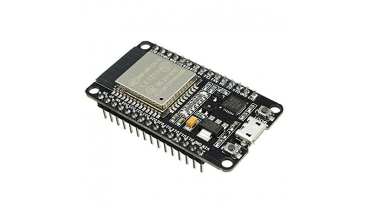
ESP32 Development Board
2. USB Type C cable to program ESP32 from a laptop or PC—most Android phones use this type of cable.
USB Type C cable
3. LED with Resistor(1K) – To test the touch
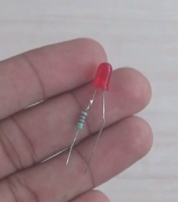
Led with resistor
4. Breadboard – To place the components
Breadboard
5. Any metal plate to sense touch. You can even use aluminium foil by connecting a wire to it.
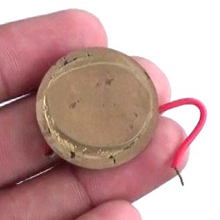
Touch Plate
Steps for the software setup:
(Ignore this step if you already have the setup of ESP boards in Arduino IDE
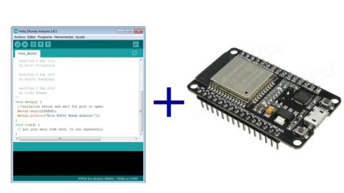
Arduino IDE + ESP32 Support
Here is the code for the ESP32: we need an Integrated Development Environment and we will use Arduino IDE software. Arduino IDE is a cross-platform application. It is written in Java and coded in C/C++ with some special rules. To download the latest Arduino IDE from here.
Arduino IDE does not contain support of ESP32 family so to install the ESP-32 Board in Arduino IDE, you can refer here.
The Code for Touch Based Home Automation System
Download the Code from the link below and Open it in Arduino IDE.
Let’s understand the code.
Before uploading you need to make some changes in the code.
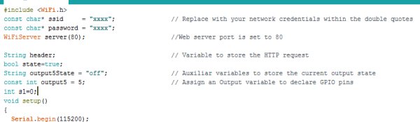
Code Declarations
The library contains all the Wi-Fi functions used in the code.
You must replace your Wi-Fi credentials here within the double quotes.
const char* ssid = “xxxx”;
const char* password = “xxxx”;
and make global declarations here.
In the Void Setup() here
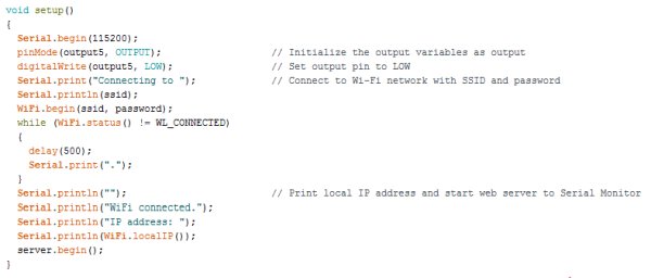
Void Setup()
We will set the Baud Rate at 115200(default speed), set outputs and initialize the Wi-Fi to connect it only one. All the code we are placing in Void Setup() runs only once after every reset.
In the void loop(), we place our main code that needs to run repeatedly.
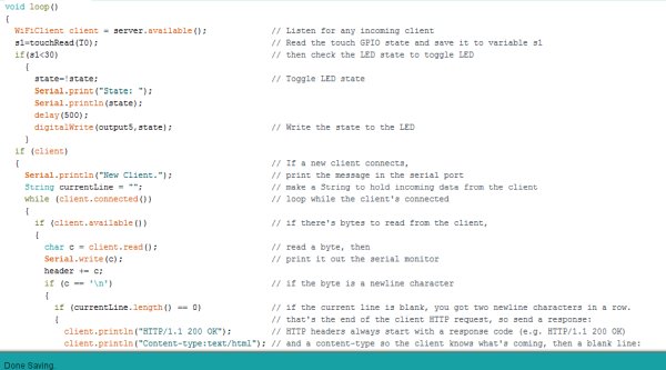
Void loop()
We can directly read the touch GPIOs using touchRead() function. We can save it to any variable and here we have saved it in the s1 variable.
Our aim is to control LED with both Touch and Wi-Fi and hence we will merge the functions in the Void loop(). An HTML page is made using the HTML script in the code here.
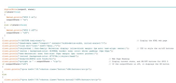
HTML page in code
You may even change this as per your application. You will see something like this in your web browser.
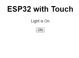
HTML Web page in the browser
Upload this code to the ESP-32 and do remember to select ESP-32 DEV Module and COM Port from Tools menu before uploading the code to the board.
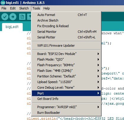
Select COM Port
Connections:
There are only one Input (Touch plate) and one Output (LED) in the circuit.
ESP-32 Pin 5 -> Resistor
ESP-32 Pin 4 -> Touch Plate(any aluminium foil or metal piece would work)
Resistor -> LED +ve
LED -ve -> Ground
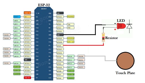
Connections
Now, power up ESP-32 with USB or a 5Volts supply and let the magic happen
Upload the code, and power up everything.
Connecting the Web server
After uploading the code, go to Open Tools>Serial Monitor. ESP32 will try to connect to Wi-Fi and display its IP address on Arduino serial monitor.
Read More Detail :IoT and Touch-Based Home Automation with Video (Hindi & English)