Summary of Introduction to Arduino Using TinkerCAD Simulator: No Hardware Required
This tutorial teaches Arduino basics using TinkerCAD (or optional hardware). It covers breadboard fundamentals, powering circuits, and five projects: single LED, blinking LED, pushbutton-controlled LED, servo control (with Serial monitoring), and temperature sensing (TMP36 in TinkerCAD, DHT11 for hardware). It explains Arduino IDE structure, common functions (pinMode, digitalWrite, analogRead/Write, delay, Serial.print), wiring conventions, and step-by-step build and code instructions.
Parts used in the Arduino Basics Workshop:
- Arduino Uno
- Breadboard
- LED
- Resistor (100 to 1k range)
- 10k resistor
- Push button
- Servo motor (micro servo)
- Jumper wires
- TMP36 temperature sensor (TinkerCAD)
- DHT11 temperature and humidity sensor (hardware)
Context and Preparation
Getting started with tinkering on Microcontrollers can often be hindered by the need to purchase hardware. In this tutorial, we offer an introduction to Arduino that requires no prior experience and no physical hardware. Instead, we will utilize an Arduino simulator called TinkerCAD. However, for those who do have the hardware, we will provide parallel instructions. TinkerCAD was chosen for its ability to closely mimic working with actual hardware—blinking lights, moving motors, and building circuits with breadboards—making it an excellent free option among various microcontroller simulators available.
Goals:
- Acquire familiarity with the standard functions and programming syntax of the Arduino language.
- -Engage with various microcontroller accessories to establish a solid groundwork for future tinkering.
List of Hardware (Optional):
For participants intending to utilize hardware during this workshop, provided below is a list of the required items:
- Arduino Uno
- Breadboard
- 1 LED
- 1 resistor (anything from 100 to 1k will work)
- 1 10k resistor
- Push button
- Servo motor
- Jumper wires
- DHT11 sensor
Circuit 1: Turning on an LED
An abbreviated introduction to breadboarding: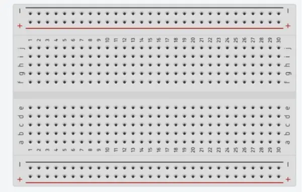
When working with a breadboard, it is essential to remember a few conventions for establishing electrical connections between components:
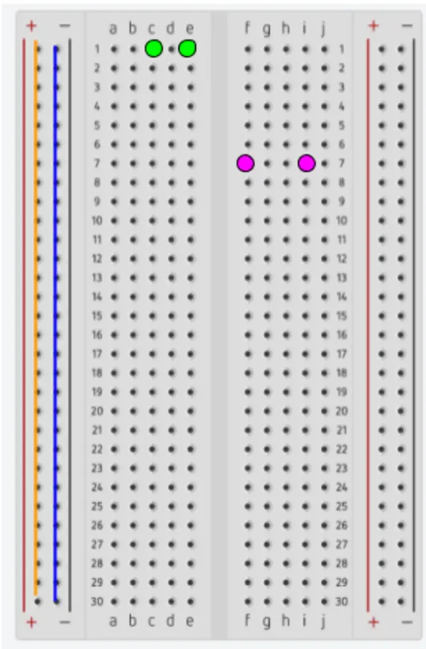
- The columns on the sides of the breadboard labeled with a ‘+’ or ‘-’ are interconnected. These columns are known as the power columns. As a result, all the holes in the first column (indicated by an orange line below) are internally connected to each other, and similarly, all the holes in the second column (marked with a blue line) are internally connected.
- a. The power columns are not interconnected, meaning there is no internal electrical connection between a hole in the orange column and a hole in the blue column.
- In the columns labeled a-e and f-j, the holes in each row are linked together. For instance, hole 1c is connected to hole 1e (green circles), and hole 7f is connected to hole 7i (pink circles).
- The separation in the board between columns e and f usually indicates a break in the internal electrical connections. Consequently, a hole in column d of a row won’t be connected to a hole in column h within the same row.
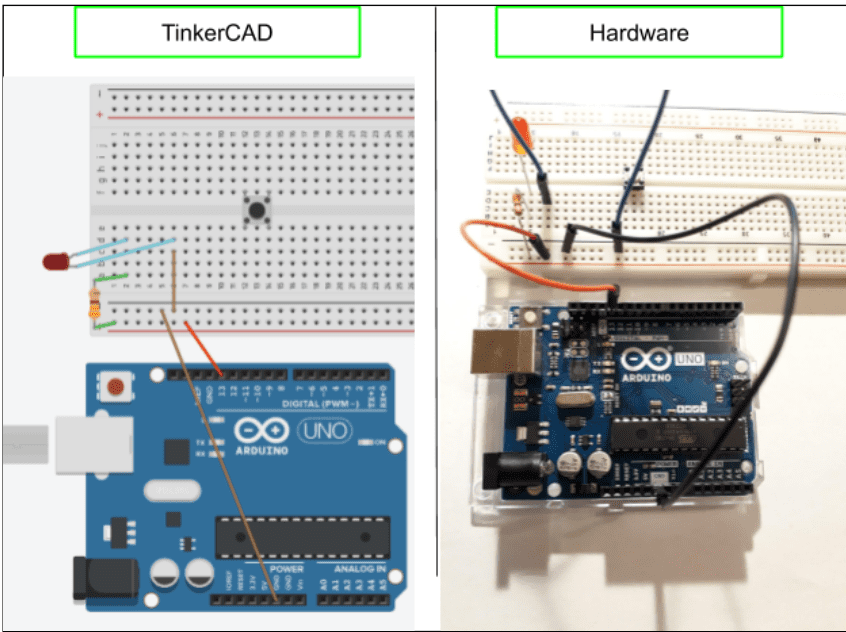
Building the Circuit:
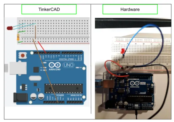
We will build the same circuit in TinkerCAD as well as with actual hardware. This setup allows us to manage the LED’s on and off states using programming.
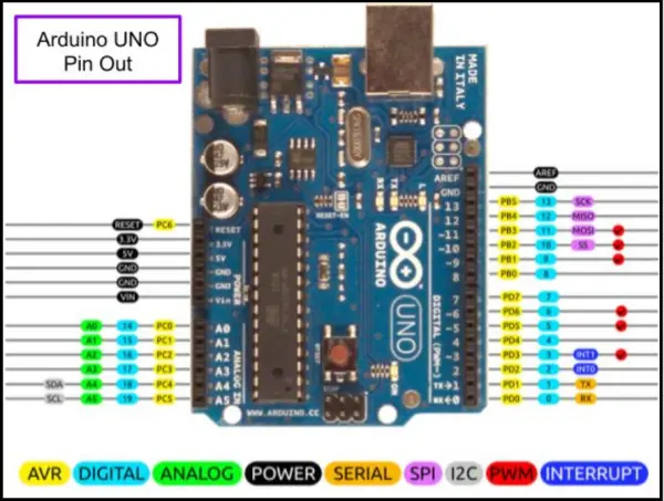
The Arduino Uno has multiple pins that function as physical inputs and outputs, each with unique capabilities. The pins consist of power, analog, digital, PWM, interrupt, I2C, Serial, and SPI pins, as shown in the widely known schematic known as the “pin-out.” In this guide, our main emphasis will be on the Power, Digital, and Analog pins, which are conveniently marked on the board’s pin-out.rya
- To initiate the circuit in TinkerCAD, access the “Circuits” option in the menu on the left side of the Dashboard, and then choose “Create New Circuit.”
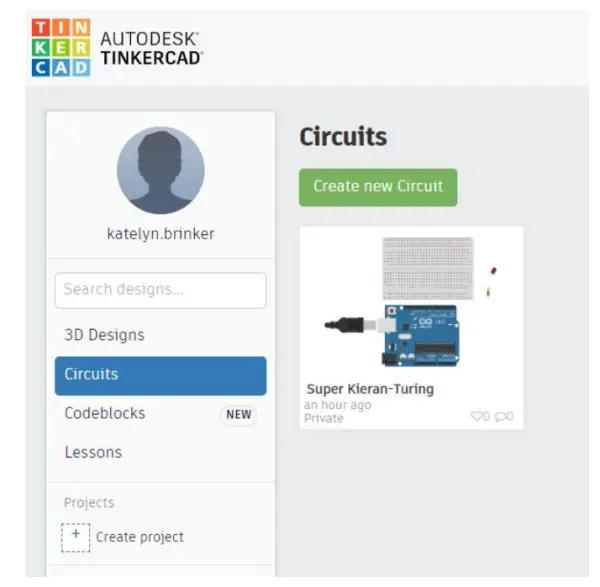
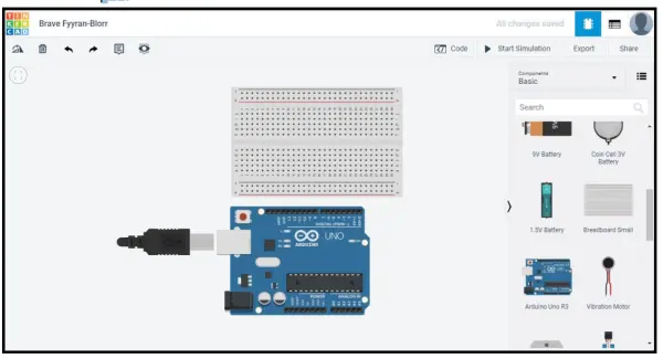
2. To incorporate components onto the canvas, simply click on them in the components menu located on the right side. Begin by adding an Arduino Uno and a breadboard to the canvas.
- After placing a component, you can click and drag to select and move it.
- Utilize the mouse scroll wheel to zoom in and out. To pan, hold down the scroll wheel.
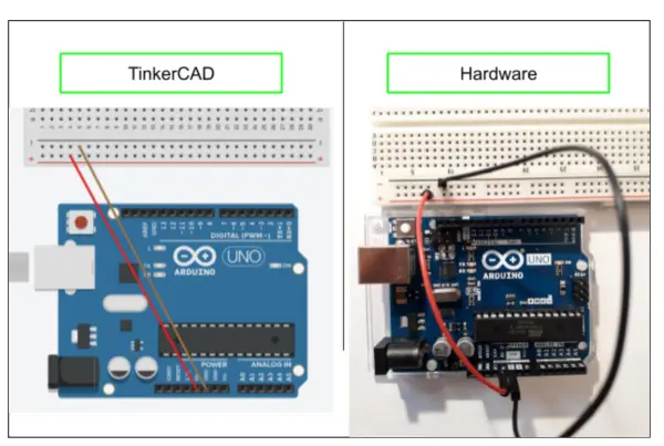
Let’s begin by establishing the power/control and ground connections between the Arduino and the breadboard.
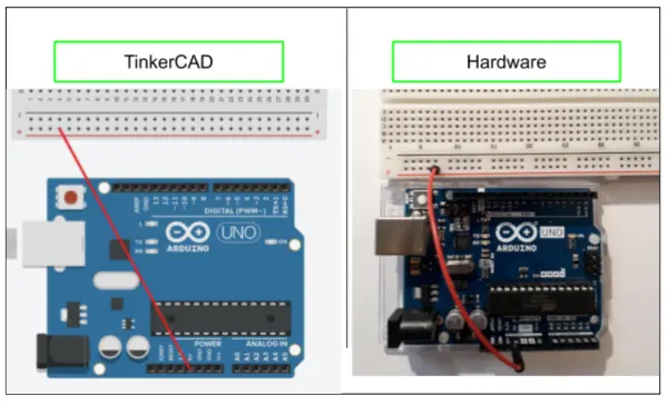
- Create a connection between the 5V pin on the Arduino and the + power column on the breadboard.
- Establish a link between the 5V pin on the Arduino and the + power column on the breadboard.
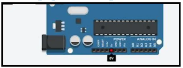
- Hardware: Connect a jumper wire from the 5V pin on the Arduino to the + power column on the breadboard.
- Establish a connection between one of the ground (GND) pins on the Arduino Uno and the – power column on the breadboard.
- In TinkerCAD, brown wires will be utilized for ground (GND) connections to facilitate easy identification.
- For hardware implementation, utilize another jumper wire to create this connection.
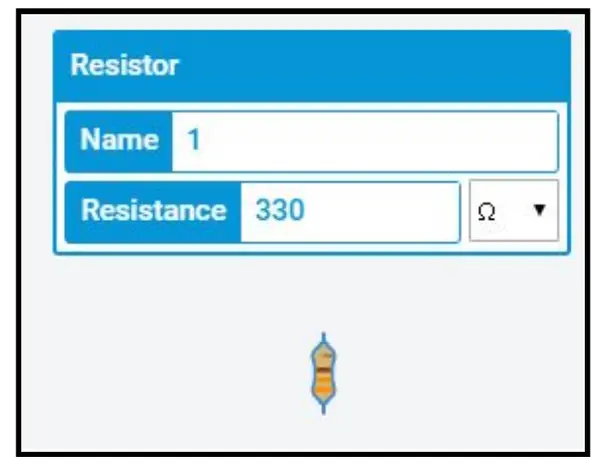
Next, we’ll incorporate a 330Ω resistor and an LED into the circuit. The resistor serves the purpose of limiting the current flowing to the LED to prevent it from burning out. The greater the resistance of the resistor, the less current will flow to the LED, making it appear dimmer.
- Place the 330Ω resistor and LED on the canvas.
- In TinkerCAD, after adding the resistor to the canvas, you will have the option to modify its value. Observe that the stripes on the resistor change color to simulate the appearance of a physical resistor with that particular value.
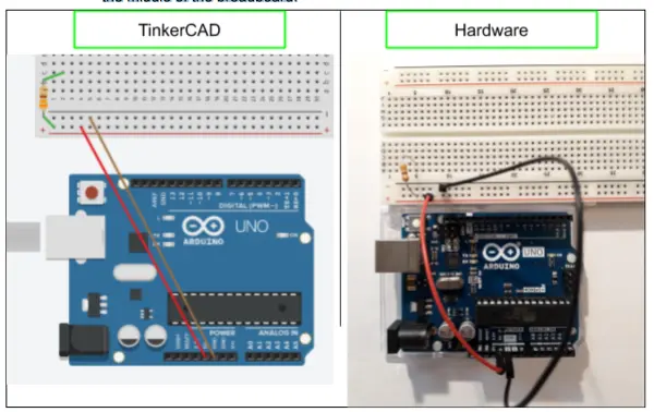
- Establish an electrical connection between the resistor and the breadboard by connecting one end of the resistor to a hole in the a-e columns of the breadboard. The other end of the resistor should be linked to the + power column. This connection effectively links the 5V pin on our Arduino to the resistor.
- In TinkerCAD, utilize wires to create the connections. A helpful approach is to position the resistor beside the breadboard, draw the connections, and then relocate the resistor onto the breadboard to clearly visualize the connections being made. The wires will move along with the resistor when you move it.
- For hardware setup, insert one leg of the resistor into the + power column and the other leg into the middle of the breadboard.
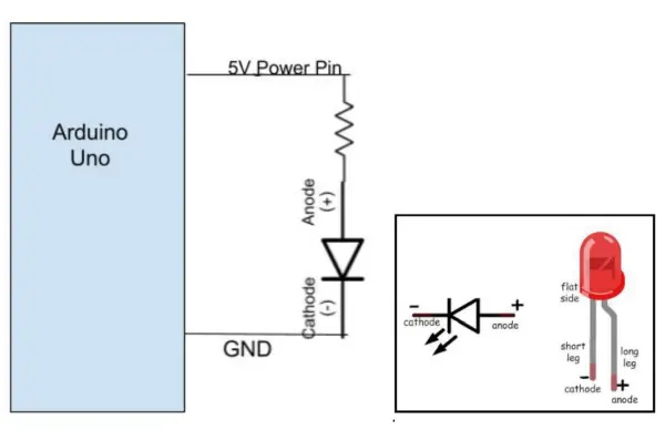
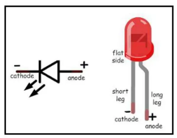
LEDs are polarized components, meaning they only function in one specific direction, while resistors are non-polarized. In a circuit, the current flows in the direction indicated by the LED/diode symbol’s arrow, which means it goes in through the anode (+) and out through the cathode (-). LEDs denote the anode and cathode in several ways:
- The legs of the LED are of two different lengths, with the longer leg being the anode.
- One side of the “light bulb” portion of the LED has a flat surface, which may be difficult to see but can be felt. This flat side indicates the cathode side.
- To remember the correct orientation of the LED in the circuit, visualize the LED symbol resembling a funnel shape.
While using TinkerCAD, hovering over one of the legs of the LED will indicate whether it’s the anode or the cathode. To rotate components in TinkerCAD, simply select the component and click the rotate button located in the upper left corner.
- Link the anode of the LED to the same row of the breadboard as the resistor, and connect the cathode to any other row. This will establish a connection between the resistor and the LED.
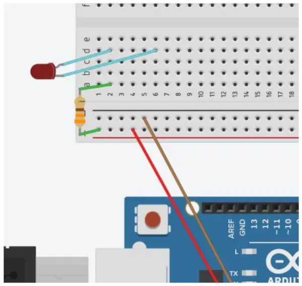
- Finalize the circuit by connecting the cathode of the LED to the – power column.
- Test your circuit by checking if the LED turns on. If the wiring is correct, the LED should illuminate.
- In TinkerCAD, click on “Start Simulation” located in the upper right corner to initiate the simulation. This will activate the USB connection and power the circuit.
- For hardware testing, connect the USB cable to the Arduino and your computer. If the Arduino is receiving power from your computer, the Arduino power light will turn off.
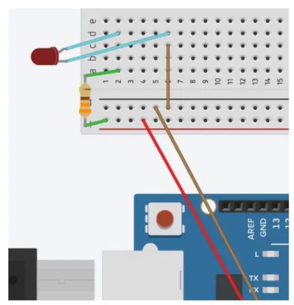
Circuit 2: Blinking LEDMoving forward, we will modify the previous circuit to program the LED to blink.
Setup the Circuit:
- Adjust the connection from the 5V pin on the Arduino to digital pin 13 (D13).
Write the Code:We recommend writing the code in the Arduino IDE and then copying it into TinkerCAD. This is because TinkerCAD automatically generates a significant portion of the code for you, which undermines the purpose of this tutorial.
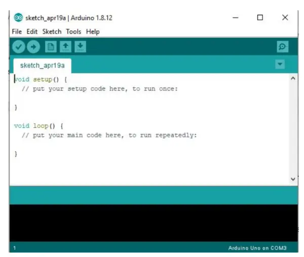
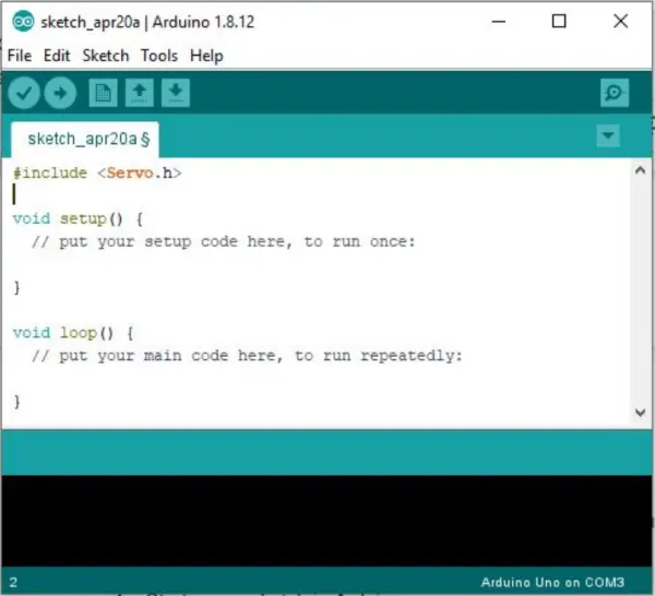
- Launch the Arduino IDE and begin a new sketch by selecting “File” and then “New.”
Within the Arduino IDE and language (also known as Arduino language), programs are referred to as sketches. In a sketch, two main components/functions are present:
- The “void setup()” function is where we establish the groundwork of the code by informing the IDE about the purpose of each pin we are utilizing. This function runs only once when the code is uploaded to the physical (or virtual) Arduino.
- The “void loop()” function serves as the main body of the code. Here, we instruct the pins on what actions we want them to perform to control the connected accessories, such as the LED. This portion of the code will continuously run in a loop until either the power is removed from the Arduino or the code is altered.
In Arduino, comments are indicated by using double slashes “//”.
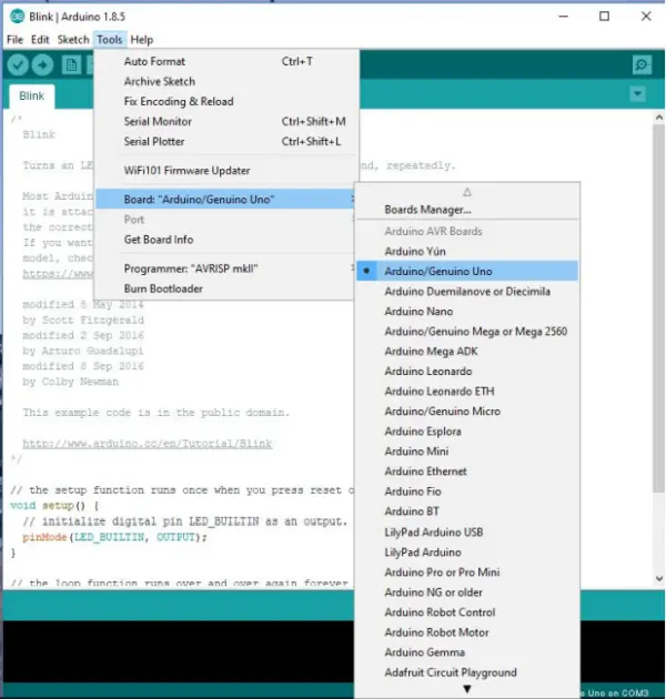
- Choose the Arduino Uno as your board in the “Tools” menu located at the top of the IDE. This selection informs the IDE about the pin assignments for proper identification.
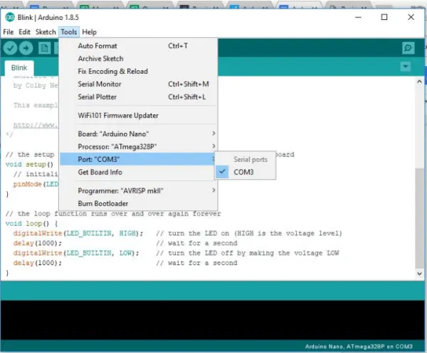
- If you are working with hardware, ensure your Arduino is connected (the power light on the board should be illuminated) and verify the correct Port through the “Tools” menu. Selecting the proper COM port is essential, as without it, your computer won’t be able to upload code onto the Arduino.
Arduino language shares similarities with C and includes various built-in functions that we will utilize in our projects. Here are the explanations for certain built-in functions, indicated by blue text featuring function names in capital letters.
Functions:
pinMode(pin, type)
– Pin: this is the arduino pin you are referencing
– Type: INPUT, OUTPUT, INPUT_PULLUP
– INPUT_PULLUP: pin is an input but will be pulled high by default
– Example: pinMode(LED_BUILTIN, OUTPUT);
digitalWrite(pin, level)
– Pin: pin you want to control
– Level: HIGH or LOW
– Pay attention to the device you are controlling. If it is active low it will be on when
the pin is set LOW
– Example: digitalWrite(13,LOW);
digitalRead(pin)
– Pin: the pin whose value you want to determine
– Often used in if statements to see if a pin meets certain conditions
– Example: digitalRead(2);
analogWrite(pin, value)
– Pin: pin you want to control
– Value: between 0 and 255. The value varies the duty cycle of the PWM signal being
written to a pin
– Example: analogWrite(A0, 27);
analogRead(pin)
– Pin: the pin whose value you want to determine
– Example: analogRead(A2);
delay(x)
– x: millisecond value that determines the duration of the delay. The next command won’t
be executed until the delay is complete.
– Example: delay(200);
Serial.print(val) or Serial.print(val, format)
– Examples:
Serial.print(78) gives “78”
Serial.print(1.23456) gives “1.23”
Serial.print(‘N’) gives “N”
Serial.print(“Hello world.”) gives “Hello world.”
Serial.print(78, BIN) gives “1001110”
Serial.print(78, OCT) gives “116”
Serial.print(78, DEC) gives “78”
Serial.print(78, HEX) gives “4E”
Code tips:
– Make sure you’re including semi-colons. Every code line you add needs to end with a
semi-colon.
– Watch your capitalization
– Make sure you’re referencing the correct pin
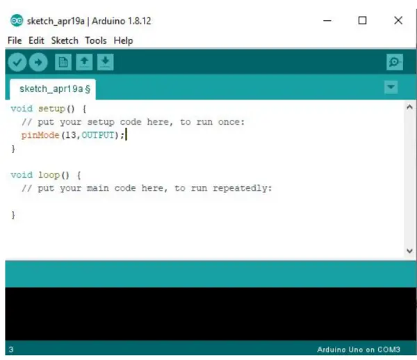
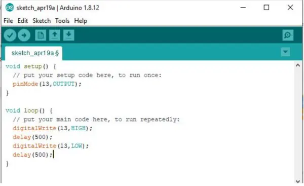
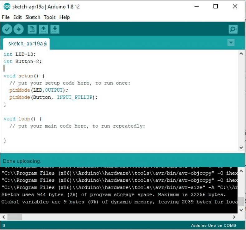
- In the setup function, configure digital pin 13 as an OUTPUT pin using the pinMode() function. Attempt to accomplish this without referring to the answer shown in the Figure below.
To achieve the blinking effect of the LED, we must control its on and off states through pin 13. Since the code inside the loop() function repeats rapidly, we introduce a delay between turning the LED on and off and turning it back on again. This delay allows us to visually perceive the blinking action of the LED.
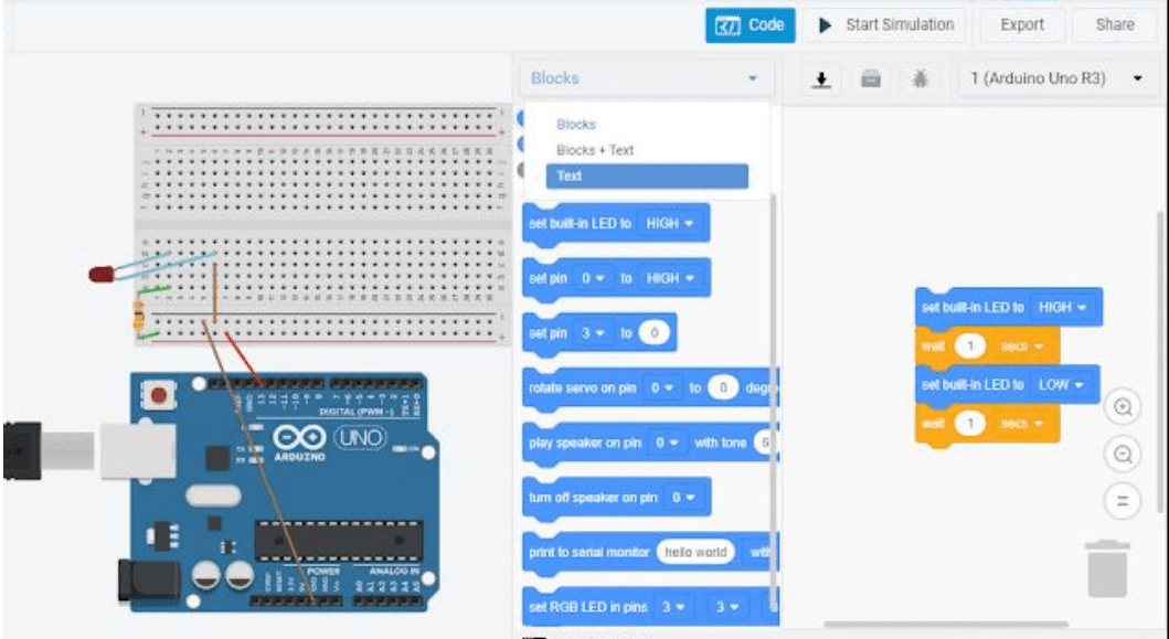
- Compose the code within the loop function to create the blinking effect of the LED using the digitalWrite() and delay() functions. Initiate the blinking with a delay of 500 milliseconds.
- Click on “Verify” (checkmark icon in the upper left-hand corner) to save and compile your code. If there are any errors, such as a missing semicolon, the IDE will display an error printout in the bottom message section.
- Once your code successfully compiles, proceed to upload it to the Arduino.
- In TinkerCAD, click on the Code button located in the upper right corner and switch from “Blocks” to “Text.” Copy your code from the Arduino IDE and paste it into the TinkerCAD code window. Then, click on “Start Simulation” to execute your code.
- For hardware usage, connect your Arduino to the computer and click on the Upload button, located adjacent to the Verify button. Clicking the Upload button will compile and then upload the code, eliminating the need to verify before every upload.
- Ensure that your hardware behaves as expected. The LED should turn on and off repeatedly.
- Next, experiment with the delays and observe the effect on your simulation or hardware. Determine the smallest delay you can use while still being able to distinguish that the LED is turning on and off.
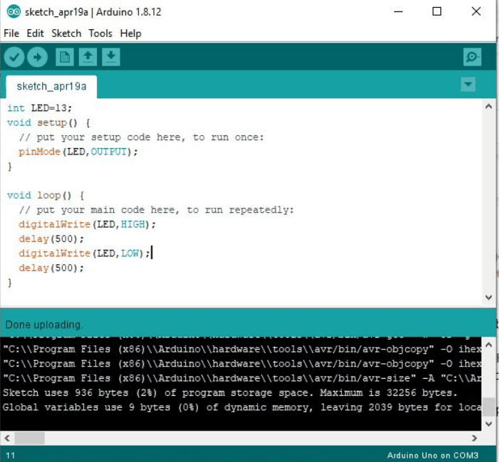
Rather than using default pin names, we can employ variables to make pin usage more intuitive. This becomes particularly beneficial when dealing with numerous pins, as it aids in keeping track of the specific functions of each pin in your code.
- Introduce a variable named “LED” to represent digital pin 13. Place this code above the setup() function, using the syntax “int LED = 13;”. In TinkerCAD, you’ll need to halt the simulation before modifying the code.
- Replace all instances of “13” with “LED” in your code. You can perform this modification either in the TinkerCAD code window or the Arduino IDE, as this is your custom code.
- Upload the modified code and verify that your hardware behaves as anticipated in response to the changes.
Circuit 3: Push Button with LED
Our circuit will soon incorporate a push button. Pressing the button will activate the LED. This procedure involves enhancing our existing breadboarding arrangement and integrating control structures into our code.
Build the Circuit:
1. Keep your blinking LED circuit unchanged. If you’re using hardware, disconnect it before constructing the pushbutton part of the circuit, as it’s not advisable to work with live hardware. In TinkerCAD, you can simply stop the simulation by closing the code window with the Code button.
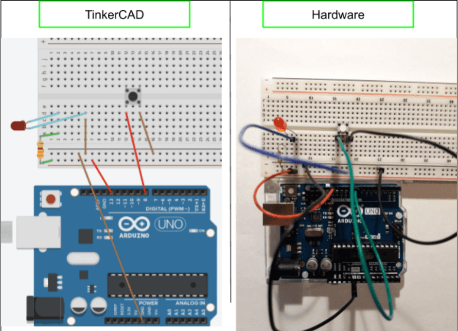
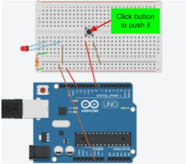
2. Integrate a pushbutton into the circuit, positioning it across the break in the breadboard for easier placement.
1. Establish a connection between the bottom left pin of the push button and digital pin 8 on the Arduino, using a red wire in TinkerCAD. Additionally, connect the bottom right pin of the push button to the – power column on the breadboard using a brown wire in TinkerCAD.
Write the Code:
As we are utilizing digital pin 8 to control the button, we must define a variable for the button and declare its pin type within the setup() function. You can modify the code you previously wrote for the Blinking LED circuit or begin a new sketch to incorporate these changes.
- Introduce a variable named “Button” and assign it the value of digital pin 8. Additionally, retain the variable named “LED” that is already set to digital pin 13.
- Within the setup() function, configure the LED pin as an OUTPUT and set the Button pin as “INPUT_PULLUP.” Since push buttons are active low devices (i.e., they are considered “on” when given a LOW signal), using INPUT_PULLUP ensures that the pin remains HIGH by default, keeping the button off by default
Control structures allow the code to follow different paths or loop depending on certain conditions. Examples of control structures consist of statements such as if/elseif/else, loops like do/while, and for loops.
Conditions are used in if/elseif/else statements to control the code’s execution. When a certain requirement is fulfilled, the program runs the code corresponding to that requirement.
if(condition)
{
Then do this code
}
elseif(condition)
{
Then do this code
}
else
{
Do this code
}
Conditions in control structures typically involve equalities or inequalities and can utilize digitalRead or analogRead to access the value of a pin.
– Example: if(digitalRead(8)==LOW)
– Example: elseif(x<12)
– Example: if(analogRead(A2)>12)
For a do/while statement, we tell the code to run over and over again until a condition is met.
do
{
This code
}while(condition)
A for loop is a control structure that allows for iteration, such as incemenenting to look through a
data set or increasing speed one notch at a time.
for (initialization; condition; increment)
{
//statements
}
The initialization should include the data type (e.g., int i=0; i<5; i++)
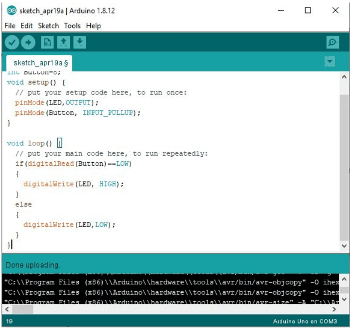
- Within the loop() function, implement an if/else statement to check if the button is pushed (digitalRead(Button) == LOW). If the button is pushed, turn the LED on using digitalWrite; otherwise, turn the LED off.
- Upload your code and perform the test.
a. In TinkerCAD, click on the push button to press it. You can hold down your left mouse button on the push button to keep it pressed.
Circuit 4: Servo Motor
Next, we will transition our attention to dealing with servos. You can choose to either build a new circuit in TinkerCAD or remove your Arduino from the breadboard since this circuit doesn’t need one. In TinkerCAD, deleting a wire or component is done by choosing it and hitting the delete key.
Servos are devices that provide precise control over position and operate as rotary actuators. With code, you have the ability to adjust their angle between 0° and 180°. It should be noted that servos are not intended for continuous rotation.
Building the Circuit
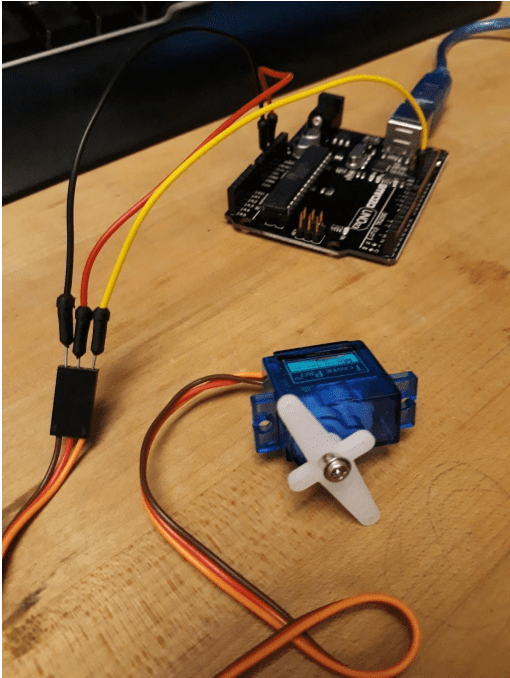
- Connect the Arduino to the servo.
a. In TinkerCAD, we’ll utilize the micro servo available in the components window.
b. Follow these wire designations/connections:
i. Brown wire: Ground ii. Red wire: 5V iii. Orange wire: Signal – connect this wire to a pulse width modulation (PWM) pin on the Arduino, marked with a ‘~’. In this case, connect it to digital pin 11.
Note: On some servos, the signal line may be white instead of orange.
Write the Code
For our code, we will utilize the servo library included in Arduino. This library offers specialized functions that make it easy to control the servo with precision.
- Begin a new sketch in Arduino
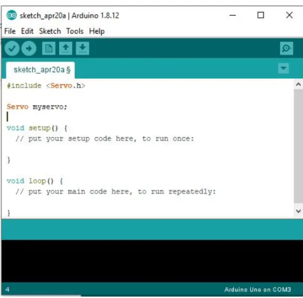
- Incorporate the servo library using the following syntax: “#include <Servo.h>”.
- a. Place this statement at the top of the code, before the setup() function.
- Generate a servo object within your code. This object allows us to manipulate its properties to set and read angles. The syntax is “Servo myservo;” and it should be placed below the inclusion of the servo library. You can choose any variable name you prefer for the servo object, such as “myservo” or any other name of your choice.
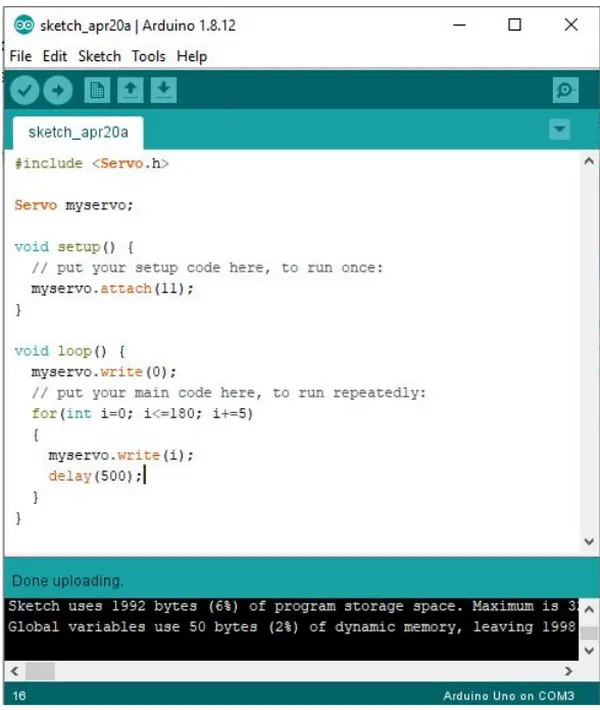
- In the setup function, we’ll attach the servo to a PWM pin instead of using pinMode. Utilize the following syntax: “myservo.attach(11);”
- Within the loop function, set the position of the servo to 0° as the starting point. Use the syntax:”myservo.write(0);” This action will also reset the servo to the 0° position at the beginning of each execution of the loop function.
- Employ a for loop to increment the angles of the servo from 0° to 180° in 5-degree increments.
a. For loop initialization: “int i = 0;”
b. For loop condition: “i <= 180;”
c. For loop increment: “i += 5;”
d. For loop body: “myservo.write(i); delay(500);”
i. The delay is introduced to allow observation of the increments in angle.
- Upload the code and observe if the servo moves as expected.
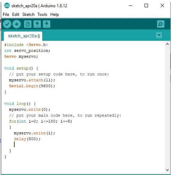
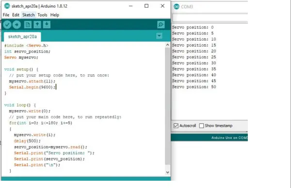
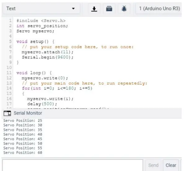
Next, we’ll enhance the code to include additional lines so that the position of the servo can be displayed on the serial monitor.
- Introduce a global variable of type int named “servo_position.”a. Note: Similar to when we created variables for the pins (LED and Button) previously, this new variable will also be a global variable placed in the same location.
- Inside the setup function, include the line “Serial.begin(9600);” This enables the usage of the serial port, allowing communication with external devices. The baud rate is set to 9600, which determines the rate of information transfer on the communication channel. A baud rate of 9600 signifies a maximum transfer rate of 9600 bits per second.
- Within the for loop, assign the value of “myservo.read()” to the “servo_position” variable. Put this line after the delay statement.
- Use Serial.print to show the servo_position value on the serial monitor. Look at the Function definitions examples given before.
- Employing “Serial.print(servo_position);” will exhibit the positions in consecutive order on the serial monitor, akin to text on a document. To have each position displayed on a separate line, a second print command must be added: “Serial.print(“\n”);”.
- Upload the code and analyze the output on the serial monitor.
- In TinkerCAD, you can reach the serial monitor button found at the bottom left corner of the code window. Press this button to see the result.
- When you’re using hardware in the Arduino IDE, you’ll locate the serial monitor in the Tools menu.
Circuit 5: Temperature/Humidity Sensor
The last circuit we will work with includes a temperature and humidity sensor arrangement. Nonetheless, TinkerCAD has restricted choices for environmental sensors, thus we will utilize the TMP36 temperature sensor in TinkerCAD and the DHT11 temperature/humidity sensor for hardware testing.
TMP36 Sensor – TinkerCAD Circuit
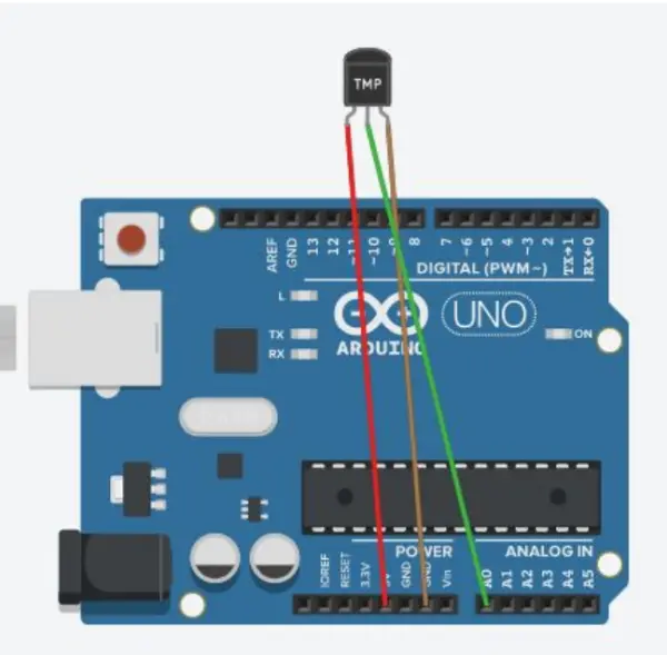
The TMP36 sensor will offer an analog output that corresponds to the temperature.
- Create a new TinkerCAD circuit and add an Arduino Uno and a TMP36 sensor to the canvas. Establish the connections between the sensor’s legs and the Arduino pins as follows: connect power to 5V, ground to the ground pin, and Vout to an analog pin – A0.
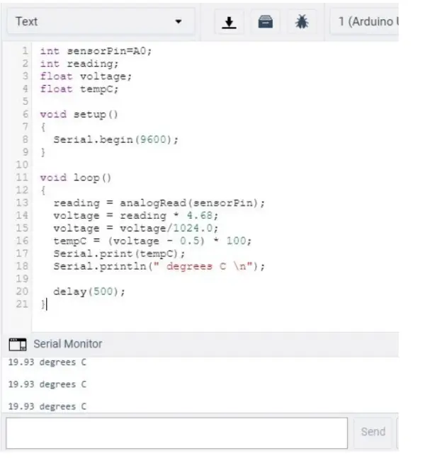
- Set up the following global variables: a. int sensorPin = A0; b. int reading; c. float voltage; d. float tempC;
- Inside the setup function, utilize Serial.begin(9600) to set the baud rate.
- Within the loop function, assign the value read from pin A0 to the global variable “reading” using analogRead(sensorPin).
- To convert the value in the “reading” variable to a temperature in Celsius, apply the following formula. You can break the formula into multiple lines, introducing intermediate variables like “voltage”:Temp (in °C) = (voltage – 0.5) * 100.0;
Please note that the voltage value should be derived using the formula: voltage = (reading * 5.0) / 1024.0
6. Display the temperature on the serial monitor and incorporate a 0.5-second delay to introduce a pause between sensor readings.
7. Upload the code and observe the values on the Serial monitor.
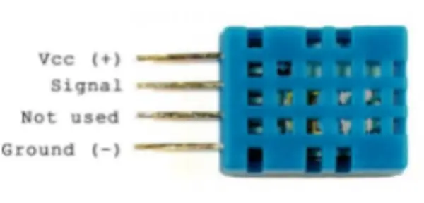
DHT11 Sensor: Hardware
The DHT11 sensor comes in two popular setups: one with 4 pins as shown, and another with 3 pins on a tiny PCB. The variant mounted on the PCB includes a pull-up resistor of 10kΩ. When using the 4-pin variation, it is important to incorporate this resistor into the circuit.
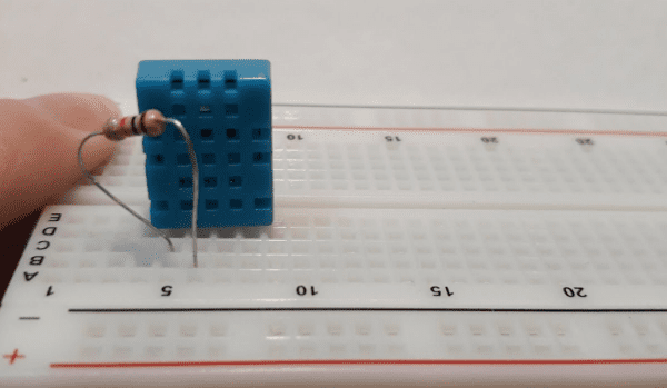
- Position the DHT11 sensor on the breadboard in such a way that each pin is inserted into a separate row.
- Establish a connection between the Vcc and Signal pin rows on the breadboard using the 10kΩ resistor.
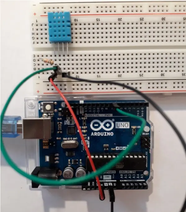
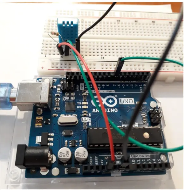
- Ensure the following connections are made:1. Connect the VCC sensor pin to the 5V pin on the Arduino.
2. Connect the ground sensor pin to the ground pin on the Arduino.
3. Connect the signal sensor pin to digital pin 7 on the Arduino.
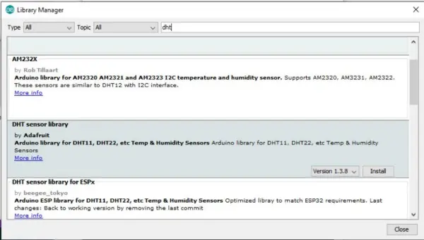
- Begin a new sketch in Arduino. If you don’t have the “dht.h” library installed yet, access the Library Manager by navigating to Tools > Manage Libraries in the top menu. Search for “dht” and proceed to install the DHT sensor library by Adafruit.
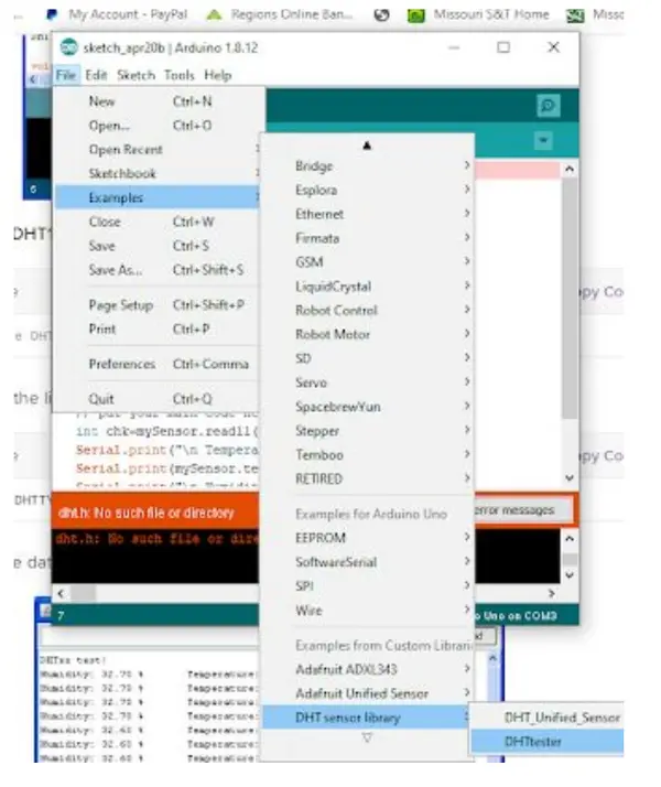
After successfully installing the Adafruit DHT library, open the “DHT tester” example sketch provided within the library.
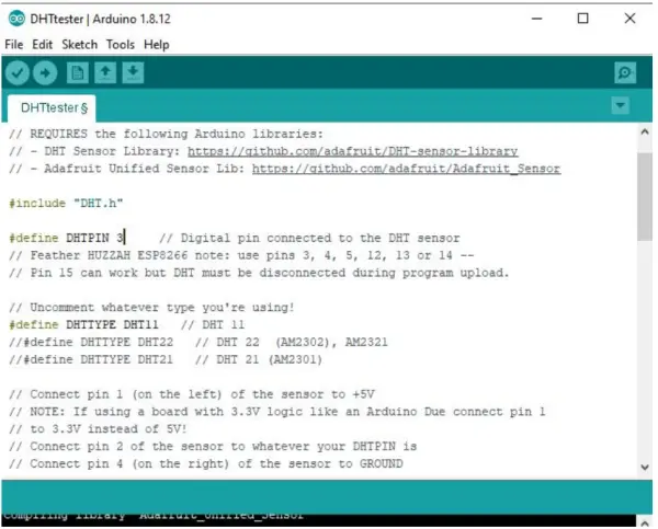
- Adjust the pin arrangement and choose the DHT11 sensor in the provided sketch as an example. Assign pin 7 to be the signal pin for the sensor.
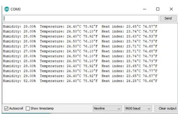
- Transfer the code to the Arduino and review the results on the serial monitor. One easy way to confirm the sensor is working properly is to softly blow air on it or adjust the temperature and monitor the displayed measurements.
- Can I do this tutorial without physical hardware?
Yes; the tutorial uses the TinkerCAD simulator so no physical hardware is required. - What pin mode should be used for a button so it stays HIGH by default?
Use INPUT_PULLUP for the button pin so it is HIGH by default. - How do I wire an LED to be controlled by a digital pin?
Connect a resistor between the 5V (or pin) and the LED anode, place the cathode to ground, and connect the control pin (e.g., D13) to the LED circuit as instructed. - How do I make an LED blink in code?
Set the LED pin as OUTPUT in setup(), then use digitalWrite(pin, HIGH), delay(milliseconds), digitalWrite(pin, LOW), delay(milliseconds) inside loop(). - Which Arduino function reads an analog sensor value?
Use analogRead(pin) to read an analog sensor value. - How do I control a servo angle in Arduino?
Include the Servo library, create a Servo object, attach it to a PWM pin with attach(pin), and use myservo.write(angle). - What sensor is suggested for temperature in TinkerCAD and in hardware?
Use TMP36 in TinkerCAD and DHT11 for hardware testing. - How do I display servo position on the Serial Monitor?
Begin Serial at 9600 in setup(), read position with myservo.read(), and print it using Serial.print. - What is the formula to convert TMP36 reading to Celsius?
Compute voltage = (reading * 5.0) / 1024.0, then TempC = (voltage - 0.5) * 100.0.