Summary of Introduction to OPAMPs and Applications
Operational amplifiers (OPAMPs) are high-performance differential integrated circuits with inverting/non-inverting inputs, power pins, and an output. They operate by saturating outputs based on input voltage differences unless negative feedback is applied to control gain via resistors like Rf and Rin. Positive feedback drives OPAMPs toward saturation for use in comparators and oscillators. Beyond basic amplification, adding components enables circuits like voltage regulators, filters, and current-to-voltage converters.
Parts used in the OPAMP Circuit:
- Operational Amplifier (OPAMP)
- Resistor Rf
- Resistor Rin
Operational amplifiers (OPAMPs) are high performance differential amplifiers in integrated form that can be used in many different ways. A typical OPAMP has a non-inverting input, an inverting input, two dc power pins, one output pin and a few other fine-tuning pins. On the following image you can see a typical diagram of an operational amplifier.
The basic OPAMP operation is simple. If the voltage applied to the inverting input is greater than the voltage applied to the non-inverting input then the output saturates to the negative supply voltage. In addition, if the voltage applied to the non-inverting input is greater than the voltage applied to the inverting input, then the output saturates at positive supply voltage.
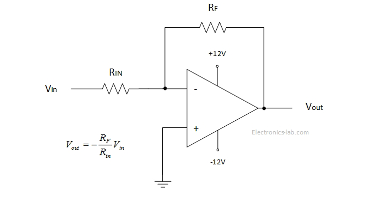
This operation mode is limited and doesn’t give us the full idea behind OPAMP operation. The trick to make an OPAMP more useful is to provide negative feedback from the output to the inverting input. In the image below we see an OPAMP with negative feedback working as an inverting amplifier.
In this configuration a part of the output voltage is fed back to the inverting input and thus the gain of the OPAMP can be controlled and output isn’t saturating. The gain of such an amplifier is controlled by the two resistors Rf and Rin. The minus means that the output is inverted relative to input.
By adding more components on the feedback loop, different OPAMP circuits can be made, such voltage regulator circuits, current to voltage converters, oscillators, filters etc.
Beside the negative feedback, a positive feedback can be used. This way the OPAMP is driven toward saturation and works in either +Vs or –Vs output range. Applications of positive feedback is on comparator circuits and oscillators.
Theory
The basic formula that gives the output voltage in respect to input voltages is as follows. This formula tells that the output voltage is a function of the input voltages difference and of the open-loop voltage gain A0.
This expression is for the ideal OPAMP and can get more complex for the real OPAMPs. Some rules apply to better understand the ideal and real OPAMPs.
Read more: Introduction to OPAMPs and Applications
- How does an OPAMP output behave when the inverting input voltage is greater?
The output saturates to the negative supply voltage. - What happens if the non-inverting input voltage is higher than the inverting input?
The output saturates at the positive supply voltage. - Can you control the gain of an OPAMP without it saturating?
Yes, by providing negative feedback from the output to the inverting input. - Which components control the gain in a negative feedback configuration?
The two resistors Rf and Rin control the gain. - What does the minus sign indicate in an inverting amplifier configuration?
It means the output is inverted relative to the input. - What applications can be made by adding more components to the feedback loop?
Circuits such as voltage regulators, current to voltage converters, oscillators, and filters can be created. - When is positive feedback used in OPAMP circuits?
Positive feedback is used in comparator circuits and oscillators to drive the OPAMP toward saturation. - Does the basic output voltage formula apply to real OPAMPs?
The formula describes an ideal OPAMP but becomes more complex for real OPAMPs.