I am twenty years old. I picked up my arduino for the first time this Christmas, and I’ve been keeping busy on my arduino applications so that I can bring you this instructable. I hope that it helps!!!
The purpose of this project was to build a stepping stone from remote controlled flight to completely autonomous flight. This initially seemed like a daunting process, but by breaking it up it becomes manageable. I think that if you have completed any kind of autonomous robot, and you have access to an RC airplane, you are in good position to take on autonomous flight. If you haven’t done so already I would HIGHLY recommend visiting the site http://diydrones.com. There are TONS of relevant threads with many helpful members. Plus, plenty of inspiration. If you’d like, please look me up; my username is waymond91.
You can buy a complete platform for developing your own autonomous flyer as well as download a complete code!!!
However, as is with many instructables members, funds are limiting, and there is limitless satisfaction trying to build it yourself from the ground up…
I had two primary objectives when beginning this project:
1) Achieve sustained level flight using our autopilot program
2) Ability to switch between radio controlled and arduino controlled flight
I strongly recommend that you already have some experience flying RC airplanes, otherwise you should look for your own plane and get some stick time. I will not be covering how to construct your own airplane, I am trying to focus on the autopilot. Maybe try and retrofit a plane you already have/
You will be at a great advantage if you already are familiar with:
The arduino programing environment (I have fun using my ubuntu terminal to download and explore new arduino libraries)
The arduino servo library
The arduino wiring library (for I2C communication – if needed)
Basic understanding of arrays and pointers
If these things are new to you, I hope my instructable is helpful. You should be able to figure it out anyways. There are lots of supplemental sites with great info!! You may want to consider trying a PING robot or a line follower 🙂
Otherwise plow on ahead!
We will be learning:
How to clean and interpret data using PID loops and cascading PID loops.
All of the videos in this instructable are found in hyperlinks, I am sorry I couldn’t get the embedding to work 🙁
Here is one of my first tests, as you can see, we still have some jittering to deal with:
http://www.youtube.com/watch?v=Im0Sm7hgn-8

Step 1: Sensors
These are standard sensors when trying to construct your own IMU (inertial measurement unit). I used ossep brand sensors based off the ADXL345 accelerometer, and MPU 3050 gyroscope. http://osepp.com/learning-centre/start-here/gyroscope-sensor-module/ & http://osepp.com/learning-centre/start-here/accelerometer-sensor-module/
The Pros of using these sensors:
Available at Frys
Code available online
I2C protocol makes wiring easy
Cons:
Headers are bigger than the actual circuit
Electric motor easily induces noise on the sensor/wires (may not be due to this specific brand)
Converting outputs to proper units took me a while
I will go over how to clean up sensor values a little later.
I do not think you should have to use I2C protocol to get this plane off the ground, it is just what was available to me at the time. There are lots of other good IMU units available online. Check Sparkfun!!
http://www.instructables.com/id/Accelerometer-Gyro-Tutorial
http://www.robotshop.com/
don’t forget adafruit
While I am adding links… I have only tried the diavolino with some success but these small arduino compatibles look like they’d fit in a model plane nicely.
http://rasterweb.net/raster/2010/11/05/cheap-arduinos/
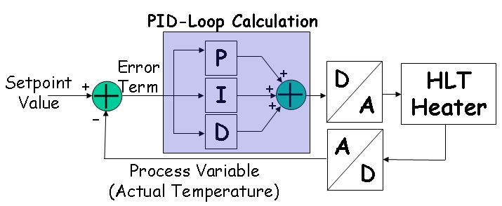
Step 2: Control Method: Proportional Integral Derrivative Control
The solution: A PID controller.
A PID controller uses three terms to calculate an output that should correct the error.
output = (kp*error)+(ki*errorSum)+(kd*dError);
The first term (the proportional term) looks at our current inputs (pitch & roll in our case) and compares it to the desired position aka setpoint (0 degrees for level flight). The calculated error (difference) is multiplied by a constant (KP) to contain the value within our output range (0 to 180 deg is servo range, but it is typically smaller once installed in an RC aircraft). Basically, the greater the error, the greater the necessary change.
The second term is the integral term. It sums all previous error (as captured by the proportional term) over time. If the error remains uncorrected for too long, the integral term grows larger thus increasing the magnitude of our output until the correction is made. Again, multiply it by you constant (KI) to contain the term within the output range *WARNING* It is possible that if you collect errors for too long the integral term will exceed your output capability. This is called INTEGRAL WINDUP. This took me a long time to fix. I was able to minimize the term by limiting the scope of time through which I viewed my error. In order to keep the first two terms from overcorrecting our error we must look to the third term.
The derivative term (dError) looks at the rate that your sensor inputs are approaching your setpoint in order to project when the error will be corrected. The derivative term can be used to slow down the output if it is correcting too fast and is likely to overshoot the setpoint. Multiply it by the constant KD to keep the output within the possible range.
The PID is a very powerful feedback controller (i.e. it uses past outputs and inputs to calculate the new output). It will greatly benefit you to do some outside reading if you have not used them before. Actually, the wikipedia page does a very good job of explaining the concepts involved. If you know calculus, the PID can become very intuitive tool. http://en.wikipedia.org/wiki/PID_controller#Control_loop_basics
Once you understand how it works, please look at the structure section on the feedforward control loop.
Step 3: Demo PID Controller
Before I threw my arduino into an airplane, I decided it would be a good idea to build a platform to test the PID on. My PID controller used the following parts:
Eflite Outrunner Motor
35 Amp ESC
11.1 V LiPo battery
1/2″ PVC
An old saw horse for a stand
The controller looks at the angle the arm is hanging at using our accelerometer and gyroscope, and uses that data to determine how much current to throw the motor in order to make the arm level.
Because the ESC is used to plug your motor into a radio reciever bus designed for servos, it is relatively easy to control a brushless AC motor with an ESC on an Arduino thanks to the Servo.h + Servo.cpp in your libraries folder. I believe the servo protocol uses pulse position modulation (PPM) which can be achieved using a PWM pin on your arduino with servo.write() function.
http://www.hooked-on-rc-airplanes.com/servo-tutorial.html
It is important to be saftey conscious when running these motors, as they go extremely fast. *ALWAYS wear saftey glasses* *Leave the propeller OFF until you absolutely need it*
For more detail: Intro to Model Airplane Autopilot