Summary of Internet Devices for Home Automation using Arduino
This article describes building Arduino-based internet-connected devices for home automation that communicate bi-directionally to control lights, motors, and power sockets. It covers prototyping with LEDs, switches, and Ethernet shields, using static IPs for addressing, and suggests one device per room plus a central distribution device. Energy savings via light sensors and dimmable lights are highlighted. Two example devices are connected directly by Ethernet during prototyping, later expandable via a router; mains relay shields are mentioned but not detailed.
Parts used in the Arduino Internet Home Automation:
- An Arduino (Uno)
- An Ethernet shield (or Wifi)
- LEDs and resistors (for output light prototyping)
- Switches (for ON/OFF or UP/DN dimmer input)
- Breadboard (for prototyping)
- Wires
- Ethernet cable
- Mains Relay Arduino Shield (for mains control, optional)
This instructable shows the principles involved in making devices to control home automation over the internet. We’re going to construct a device (or several of them), that talk to each other over the internet to control lights, motors for curtains/blinds, power sockets etc.
In contrast to devices controlled from a web browser or phone, these are designed to be simple, Arduino based devices that are capable of talking to each other bi-directionally. They may be in the same house or in different buildings and may have one way communication (e.g. a light switch and light) or two way (e.g. an automation controller).
It’s possible to have local Device/Relay combinations to control Mains socket power to TVs, Computers etc..
Also you could see this working in building control. Commercial examples that work over local or proprietary interfaces are : Clipsal C-Bus, X10, Bus-SCS.
The Picture shows an example of what we’re trying to achieve using the commercial C-Bus devices as an example.
(http://en.wikipedia.org/wiki/File:CBus_Wiring.gif). But in our case the C-Bus is replaced by the Internet or a Local Network.
Practically speaking, it would make most sense to have one device per room with several switches, sensors and possibly low-voltage motors wired into it, and one device at the distribution board controlling relays or dimmers.
A major factor in Energy Waste is having Lights on too brightly during periods when a room is adequately lit from Natural Light. Adding a Light Sensor Device in a Room with a Dimmable Light Device significantly increases Energy Efficiency by controlling the Room Light in response to the sensed light in the room.
==========
By the way. If you like this Instructable, you might also like:
Digital Thermometer for your Home:
http://www.instructables.com/id/An-Arduino-Thermometer-with-Digital-Display/
Internet-Radio:
http://www.instructables.com/id/Arduino-Raspberry-Pi-Internet-Radio/
Make your own “Wii-Remote” like control of a PC Flight Simulator
http://www.instructables.com/id/Flight-Simulator-with-Arduino-and-Python/
==========
Step 2: Prototyping the Arduino Internet Device
We’ll be concentrating on the principles of the Device itself.
To do that we’ll be prototyping it with LEDs and Switches. Once the Arduinos are talking and controlling LEDs, making it work with Mains Relay shields and motor shields is straight forward.
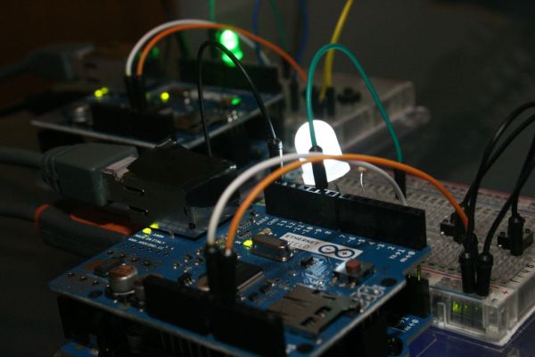
We’re going to construct a device with switches and LEDs, and we’ll connect 2 of them over Ethernet. That way we’ll be protoyping both the Switch function and the Light Control function at the same time and demonstrating bi-directional comm’s.
For many Devices we should connect them via a Router. If we only have 2 devices (as we do here) then we can connect them to each other. The Ethernet IC takes care of the required Crossover.
We need to give some thought to how one device knows the address of the device it wants to communicate with.
Here’s how we’ll approach it:
Each Device has its own static-IP address. Each Device “knows” which device it wants to talk to. Therefore we can hard-code the Static-IP address of the destination device in the Arduino Code of the Transmitting Device. Not the most elegant solution. But completely practical.
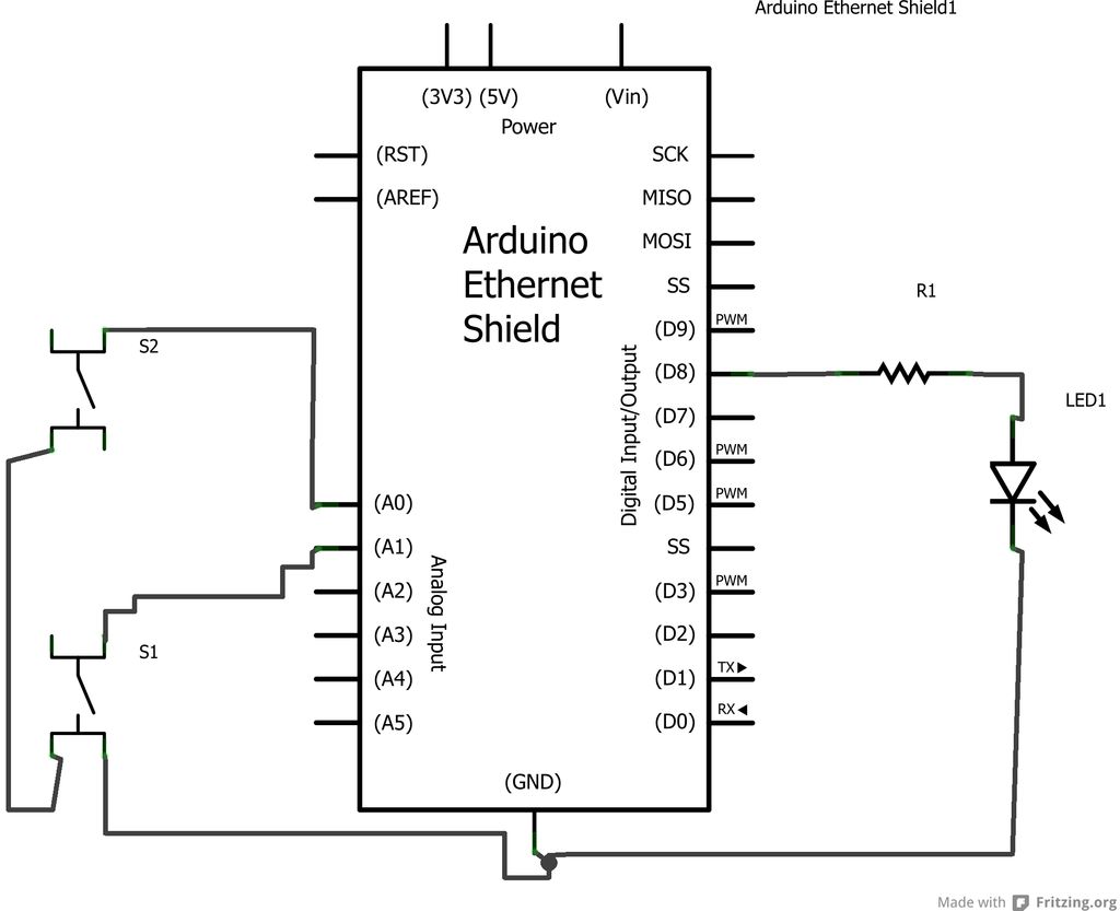
Step 3: Connect the Circuit
Build an example Device as shown in the diagrams. In fact, build two of them. We’ll need one to talk to the other.
Each Device consists of:
1. An Arduino (Uno)
2. An Ethernet Shield
3. An LED and Resistor to represent an Output Light.
4. Two Switches to represent an ON/OFF Switch panel or UP/DN Dimmer (for example).
Once you’ve built them plug both into your PC USB for programming.
Plug an Ethernet cable from Device 1 to Device 2 (the crossover is taken care of in the Ethernet Shield).
* An Arduino (Uno)
* An Ethernet shield (or Wifi)
To prototype:
* A breadboard
* Some LEDs, Wires and Switches
For Mains Control:
* A Mains Relay Arduino Shield (e.g. http://www.dfrobot.com/index.php?route=product/product&product_id=496)
We won’t be covering the Mains Control because it’s covered in lots of tutorials and there are a lot of shields available
For more detail: Internet Devices for Home Automation using Arduino
- How do the devices communicate with each other?
Devices communicate bi-directionally over the internet or a local network using Ethernet (or WiFi) shields on Arduinos. - Can two prototype devices be connected without a router?
Yes, two devices can be connected directly with an Ethernet cable because the Ethernet shield handles crossover. - How does a device know which other device to talk to?
Each device uses a hard-coded static IP address for the destination device in the Arduino code. - What components are needed for prototyping the device?
An Arduino Uno, Ethernet shield (or WiFi), LEDs, resistors, switches, breadboard, wires, and an Ethernet cable are used for prototyping. - Does the article cover mains power control details?
No, mains control is mentioned but not covered in detail; it refers to existing tutorials and available relay shields. - What is a suggested deployment layout for these devices?
One device per room with switches, sensors, and motors, plus a device at the distribution board for relays or dimmers. - How can energy efficiency be improved using these devices?
Adding a light sensor in a room with a dimmable light device lets the system adjust light levels based on natural light, reducing energy waste. - Is two-way communication supported for all device types?
Devices may be one-way (e.g., a switch and light) or two-way (e.g., an automation controller), depending on design.