Summary of How to make Arduino Laser Turret using Servo motors and Joystick
This project builds an Arduino-controlled two-axis laser turret using two micro servos and a PS2-style analog joystick, with 3D-printed mounting parts and a laser diode. The joystick analog inputs map to servo angles via Arduino code, enabling smooth pan and tilt control. The guide covers 3D printing, cleaning parts, wiring servos and joystick to Arduino Uno, uploading code, and final assembly. Power is supplied from a battery pack to the Arduino, which provides 5V to the breadboard and components.
Parts used in the Arduino Laser Turret:
- Arduino Uno
- Jumper wires
- Breadboard
- Joystick module (PS2 style analog joystick)
- 2 micro servos
- Laser diode
- 7.4V lithium-ion battery pack
- USB programming cable
- 3D printed parts (STL files provided)
- Screws (for mounting servos)
- Double-sided adhesive
- Hobby knife (for cleaning prints)
- Arduino IDE (software)
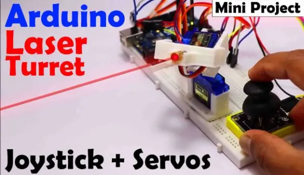
Arduino Laser Turret, Overview:
In this endeavor, I will show how to construct an Arduino laser turret with servo motors and a two-axis joystick. I will supply the code needed along with a circuit diagram, along with a thorough explanation of the project. This will allow anyone to construct the laser turret without facing any challenges.
What is Arduino Laser Turret?
This task includes a simple tool made up of a two-way servo system with a laser component, operated by a PS2 style joystick. You may be curious about the practical applications of this project, and the response varies based on the particular situation. Allow me to offer some instances to demonstrate its potential practicality.
Take into account a 4WD-capable robot that is controlled via Bluetooth. By affixing a camera to its head, we are able to not just see what is in front but also capture side and top angles. The idea of this project stays consistent, even though the modules are replaceable.
Another use case encompasses integrating a water sprinkler into an Arduino robot designed for firefighting. We can direct the water pipe to accurately water specific areas. These instances show that the project can be utilized in different situations.
After introducing the idea, we will explore the different phases of the project in a step-by-step manner for easy comprehension.
Designing
I have used a 3D printer to make the required parts for the servo mechanism section of this project. There’s no need to worry if you are a beginner in designing and creating your own 3D prints. I have given STL files that are specifically made for this project, which you can utilize to conveniently create the necessary components.
Download 3d Files:
After acquiring the STL files, the following step is to get them ready for printing. This includes cutting the design, which can be accomplished by utilizing the popular Cura slicer software. Through the use of Cura, you can transform the 3D model into a compatible format for your 3D printer to accurately print.
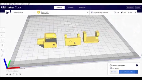
It took more than three hours to print the parts for this project. In my situation, I selected white PLA filament for the material used in printing, however, you can choose any color that works best for you. Making sure you have chosen the adhesion option in your 3D printer settings is crucial. As we are printing three parts at once, it is crucial to resolve any possible problems with one part in order to guarantee the successful printing of the remaining two.
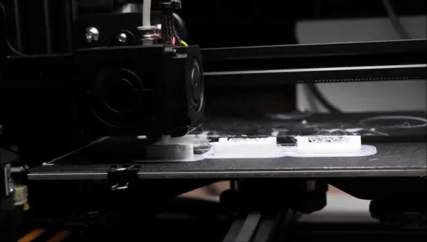
Once the printing process is finished and the printed components are in hand, some basic cleaning is necessary. A web-like pattern can often be seen on the printed pieces because supports were not utilized in the printing process. Adding direct supports to the process would increase the total printing time.
In the picture below, you can observe the web-like structure being cleared with a hobby knife.
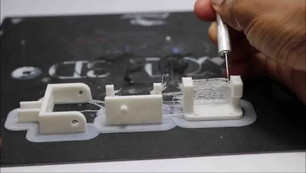
Cleaning and removing the web-like structures from the printed parts can be time-consuming, especially since the same process must be done for all three parts. Nevertheless, after finishing the cleaning procedure, you will have the components displayed in the image below.

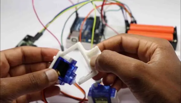
With the main mechanism now ready, it is time to put together the different components. Before starting the assembly, make sure you have collected all the required parts. Now that the primary mechanism is prepared, we can proceed to the next phase of the project.
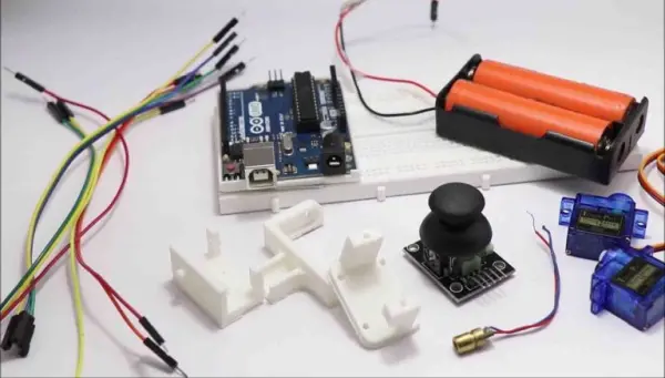
We will gather all the materials listed below, as shown in the image provided.
– Arduino Uno
– Jumper wires and breadboard
– Joystick module
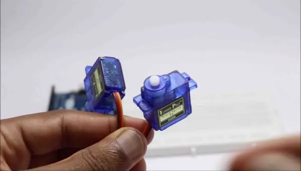
– 2 micro servos
– Laser diode
– Arduino IDE
Having gathered these components, we can proceed with the assembly and implementation of the project.
Circuit Diagram For Arduino laser turret:
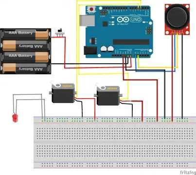
To simplify the process, let’s go through the circuit building step by step, focusing on each component individually.
There are two main components in this circuit: the micro servos and the PS2 module.
Micro servo connections
The micro servo is made up of three pins: two for the power source (positive and negative) and one for the signal. Based on the circuit diagram, the power rails on the breadboard are connected to the positive and negative pins of both servos. The servos’ signal pins are connected to pins D3 and D4 on the Arduino Uno.
In this assignment, the servos manage the controlling of the up-down and swinging movements. The horn of the second servo has a holder to keep the laser module secured.
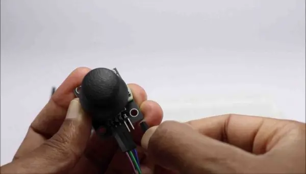
Analog joystick module
The joystick module comprises four pins, of which two are dedicated to the power supply, and the remaining two are used for vertical and horizontal control.
To make the connections, we need to link the positive (+) and negative (-) terminals of the joystick module to the power bars on the breadboard. Moreover, the Vrx pin is connected to A0 while the Vry pin is connected to A1 on the Arduino Uno board.
Regarding the laser diode, it can be linked directly to the power rails on the breadboard, where the +5V and GND pins from the Arduino Uno are connected.
Once these connections are set up, the circuit is fully operational, and we can move forward with uploading the codes to the Arduino Uno.
Arduino laser turret code
To upload the code to your Arduino Uno, follow these steps:
1. Connect the programming cable to the Arduino Uno.
2. Open the Arduino IDE.
3. Check the port number and board type by navigating to “Tools” and selecting the appropriate options for “Board Type” and “Ports.”
4. Copy the provided code and paste it into the Arduino IDE.
5. Click on the “Upload” button to initiate the upload process.
6. Once the upload is complete, disconnect the programming cable from the Arduino Uno.
By following these steps, you will successfully upload the code to your Arduino Uno and can proceed with the next stages of the project.
Some basics about the code
We start the code by #include <Servo.h> that means we are telling the IDE to include servo library so that it can understand with what module we are trying to communicate
After this we are calling functions for Joystick and then assigning the pin numbers for servos these are called as
|
1
2
3
|
servo1.attach(3);
servo2.attach(4);
|
and
|
1
2
3
|
int joyX = 0;
int joyY = 1;
|
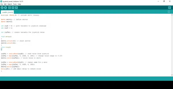
Now, we need to assign values that determine how the servo should respond when it receives input from the joystick module.
joyVal = analogRead(joyX);
joyVal = map(joyVal, 0, 1023, 0, 180);
servo1.write(joyVal);
joyVal = analogRead(joyY);
joyVal = map(joyVal, 0, 1023, 0, 180);
servo2.write(joyVal);
delay(20);
The delay parameter represents the amount of time allocated to the servo. Increasing the delay value results in a slower response, as it allows for smoother movements and helps eliminate any unwanted noise or vibrations.
Final assembly
After you have uploaded the code successfully, it is important to test all the functions to make sure they are functioning correctly. Through comprehensive testing, you can confirm that every component and function is working as anticipated. After you have completed all the individual tests successfully, you can then move on to the assembly of all the components.
To start putting together the servo, first connect the bottom piece. Insert the servo into position and fasten it with screws. If you don’t intend on using the servo for other projects, you can also glue it in place with superglue.
Perform the identical procedure on the another servo, ensuring it is firmly fastened.
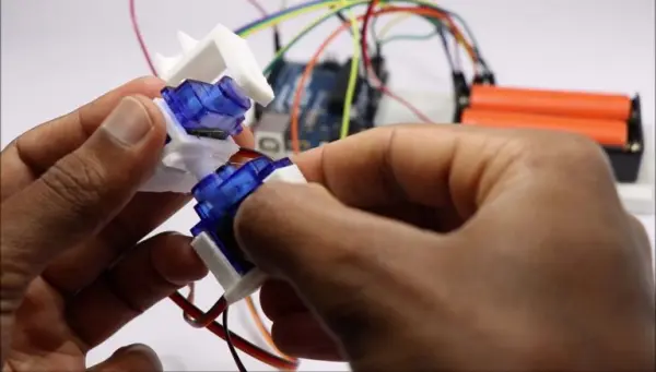
Then, connect the diode holder to the horns that have been attached to the 3D printed component. This will guarantee that the laser diode stays firmly fixed while in use.
Once you have completed the previous step, you can connect the two servos together using a base servo. This base servo will be responsible for the swinging action of the mechanism.
Next, secure the entire assembly onto a breadboard using a piece of double-sided adhesive. On the other hand, you could opt for a personalized 3D printed container, although it’s not advisable because of its restrictions.
Afterward, attach the joystick module to the edge of the breadboard. In this configuration, an Arduino is powered by a 7.4V supply from a lithium-ion battery pack. The Arduino then provides 5V power to both the breadboard and any additional components linked to the power rail.
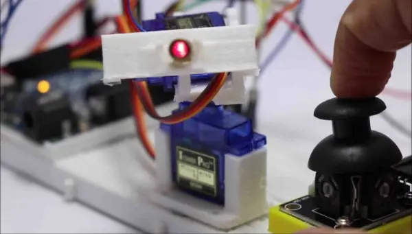
Just plug in the power source, and you’ll be able to see your laser working! Using the analog joystick allows you to alter the laser’s direction, giving you a gaming-like feel.
Our goal is to improve this project in the future by converting it into a laser turret that is completely controlled wirelessly. Furthermore, our goal is to create a WiFi camera for a car controlled by a PS2.
We trust that you found this project captivating, and we have more thrilling projects in store for the future. Thank you, and don’t hesitate to share your thoughts and feedback.
- What is the Arduino Laser Turret?
A simple pan and tilt system using two micro servos and a laser diode controlled by a PS2-style analog joystick and an Arduino Uno. - How are the servos connected to the Arduino?
The servos power pins are connected to the breadboard power rails and their signal pins are connected to digital pins D3 and D4 on the Arduino Uno. - How is the joystick wired to the Arduino?
The joystick + and - are connected to the breadboard power rails and Vrx and Vry are connected to analog pins A0 and A1 respectively on the Arduino Uno. - How do you power the system?
An external 7.4V lithium-ion battery pack powers the Arduino, and the Arduino supplies 5V to the breadboard and components. - What does the provided Arduino code do?
It reads analog joystick values, maps them from 0-1023 to 0-180 degrees, and writes those angles to the two servos with a small delay. - How long does printing the 3D parts take?
Printing the three parts took more than three hours in the described build. - Do the 3D prints require cleanup?
Yes, printed parts show web-like structures that are removed with a hobby knife since supports were not used. - How is the laser diode mounted?
The laser diode is secured in a diode holder attached to a servo horn on the 3D-printed mount. - Can the project be expanded later?
Yes, the author plans wireless control and a WiFi camera integration for future versions.