
Summary of Input Pullup Serial using Arduino
This article demonstrates an Arduino project that uses the INPUT_PULLUP mode with pinMode() to monitor a switch's state. It establishes serial communication between the Arduino and a computer via USB. The onboard LED connected to pin 13 illuminates when the input is HIGH (switch open) and turns off when LOW (switch pressed).
Parts used in the Input Pullup Serial using Arduino:
- Arduino Board
- A momentary switch, button, or toggle switch
- breadboard
- hook-up wire
This example demonstrates the use of INPUT_PULLUP with pinMode(). It monitors the state of a switch by establishingserial communication between your Arduino and your computer over USB.
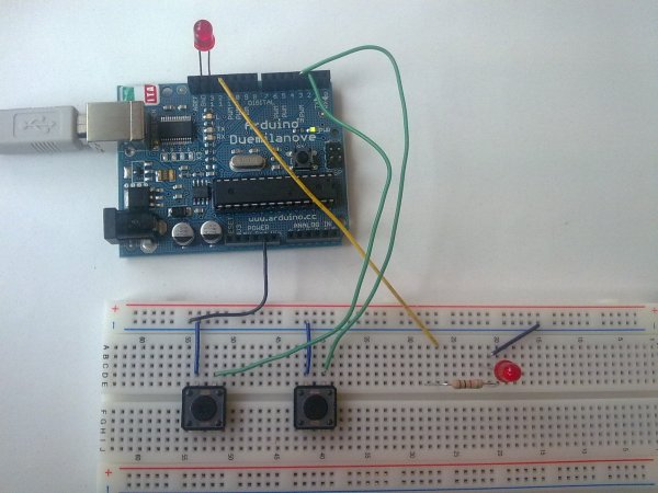
Additionally, when the input is HIGH, the onboard LED attached to pin 13 will turn on; when LOW, the LED will turn off.
Circuit
image developed using Fritzing. For more circuit examples, see the Fritzing project page
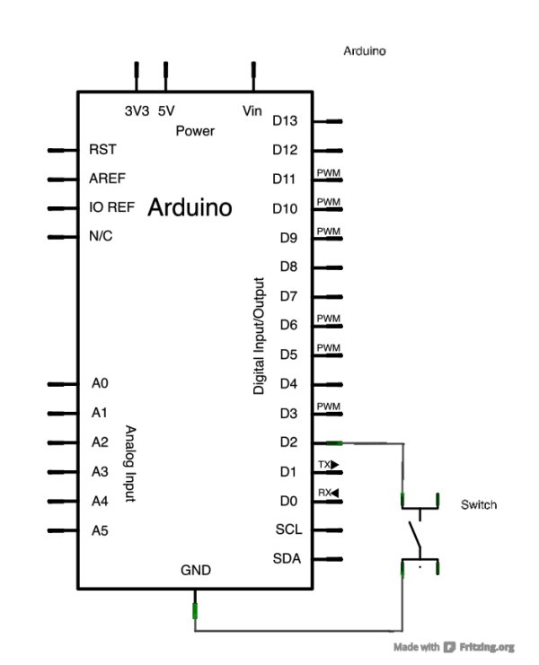
Connect two wires to the Arduino board. The black wire connects ground to one leg of the pushbutton. The second wire goes from digital pin 2 to the other leg of the pushbutton.
Pushbuttons or switches connect two points in a circuit when you press them. When the pushbutton is open (unpressed) there is no connection between the two legs of the pushbutton. Because the internal pull-up on pin 2 is active and connected to 5V, we read HIGH when the button is open. When the button is closed, the Arduino reads LOW because a connection to ground is completed.
Schematic
Code
In the program below, the very first thing that you do will in the setup function is to begin serial communications, at 9600 bits of data per second, between your Arduino and your computer with the line:
Serial.begin(9600);
Next, initialize digital pin 2 as an input with the internal pull-up resistor enabled:
pinMode(2,INPUT_PULLUP);
The following line make pin 13, with the onboard LED, an output :
pinMode(13, OUTPUT);
Hardware Required
- Arduino Board
- A momentary switch, button, or toggle switch
- breadboard
- hook-up wire
For more detail: Input Pullup Serial using Arduino
- How does the internal pull-up resistor affect the reading?
The internal pull-up on pin 2 is active and connected to 5V, so we read HIGH when the button is open. - What happens when the pushbutton is closed?
When the button is closed, the Arduino reads LOW because a connection to ground is completed. - At what speed does serial communication start?
Serial communications begin at 9600 bits of data per second between the Arduino and the computer. - Which pin controls the onboard LED?
Pin 13 is configured as an output to control the onboard LED. - What command initializes digital pin 2 as an input?
The line pinMode(2,INPUT_PULLUP) initializes pin 2 with the internal pull-up resistor enabled. - Can I use different types of switches for this project?
Yes, a momentary switch, button, or toggle switch can be used. - Does the LED turn on when the button is pressed?
No, the LED turns off when the button is pressed because the input reads LOW. - What tool was used to develop the circuit image?
The circuit image was developed using Fritzing.
