A rotating machine that is controlled by a robotic glove. Neverending fun.
Step 1: Concept

Our seminar assignment was to design a useless machine. Thinking about absurd tasks, we were inspired by the greek myth of Sisyphus and the idea of gravitational weight shifting in an endlessly repeating mechanism. We wanted to add user control to make it into a sort of game, so we implemented sensors in form of a robotic glove. It’s kind of fun, we promise! And the fun never ends…
WHAT YOU NEED:
1x Arduino Mega 1x Breadboard 4x Stepper motor 28BYJ-48 4x Stepper driver ULN2003
A lot of cables Screws, nuts and spacers
And for the glove: Velostat Masking tape, Female cables Thin plastic sheet A glove Needle and thread
Step 2: Making the Box: Laser Cutting
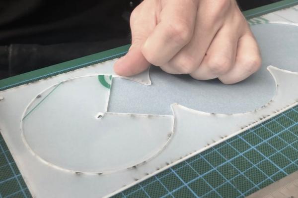
We attached a .pdf with the laser cutter files, everything fits on a 50 x 25cm plate of 2mm plexiglass. We prepared a few different rotary elements for you to play with 🙂
The files have the exact hole dimensions of the motor, which will result in a bit loose connections because of the laser melting away a bit of the plexiglass. Scaling the holes by .94 to ensure a press-fit and not having to glue them to the motor shafts worked well for our laser cutter settings (if you want to scale the motor shaft holes as well, remember to keep them centered to their position).
It’s best to leave the protection layer on the plexiglass until the very end to keep it nice and clean.
Step 3: Making the Box: Backplate and Casing
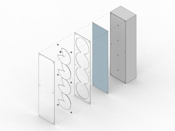
We used 3mm kappa print sandwich panels for the backplate. You need to cut holes for the screws and the motor shafts. Don’t worry about being precise, we will cover it up with a thinner, easier to cut paper. Once that is done, you can start mounting the motors and their drivers to the backplate. We just screwed them onto it, using chops of wood and cardboard that we found. If you are feeling fancy, you could also make the box out of wood.
Now you can cut and assemble the side pieces of the casing.
Step 4: Making the Flex Sensor Hand
For user control, we made our own robotic glove out of bending sensors. We tried different methods for making the sensors (like aluminium foil and pencil lead) but what worked best for us was the Instructable by tonll using velostat(https://www.instructables.com/id/DIY-Bend-Sensor-Using-only-Velostat-and-Masking-T/) – highly recommended!
You will need four of these sensors and then sew them onto the gloves.
Once you’ve assembled the glove, you need to calibrate the sensors. If you print the values and adjust STRAIGHT_RESISTANCE and BEND_RESISTANCE, you should get the correct bending angle of your fingers.
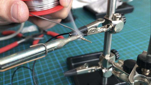
Additionally, we needed to solder 8 cables of 1,20m length to connect the sensors from the glove.
Step 5: Hooking Everything Up
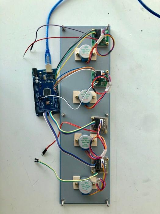
Now it’s time to hook everything up. If you follow the included Fritzing diagram everything should work fine. Remember not to use pins 0 & 1 for the motors since they are used by the arduino for the serial communication.
Step 6:
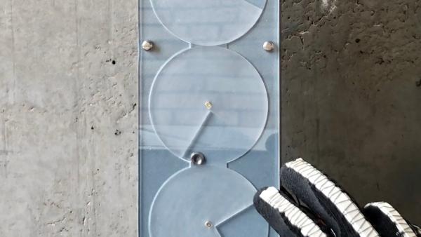
Finally, you can remove the protective layer of the plexiglass and assemble all the pieces. We used sandpaper on the rotating pieces for a nice frosted effect. Don’t forget to include the little button that will be moved around. We also added a thin removable layer of plexiglass to slide into the backside, just to keep the cables in place. This way we can still access all the electronics on the inside.
Source: Infinite Jest