Summary of IMU Interfacing Tutorial Get started with Arduino and the MPU 6050 Sensor
This article reviews basic IMU sensors compatible with Arduino, highlighting the MPU 6050 as the most reliable and cost-effective option. It explains the functions of accelerometers and gyroscopes, details the hardware setup using I2C communication, and provides a step-by-step guide to interfacing the sensor with an Arduino board via specific pins and libraries for data visualization.
Parts used in the Arduino MPU 6050 Project:
- Arduino or an Arduino clone board (Freeduino)
- MPU 6050 sensor
- Interconnecting wires
- Arduino IDE software
- Processing IDE software (optional)
- Jeff Rowberg MPU6050 library
- I2Cdev library
In this post, I will be reviewing a few basic IMU (Inertia Measurement Unit) sensors that are compatible Arduino. I will also give a short tutorial for interfacing an Arduino with the best IMU sensor available. IMU sensors like the MPU 6050 are used in self-balancing robots, UAVs, smartphones, and more.
IMU sensors are one of the most common types of sensors used today in all kinds of electronic gadgets. IMU sensors help us in getting the attitude of an object, attached to the sensor in three-dimensional space. These values are usually in angles to help us to determine its attitude. They are used in smartphones to detect their orientation or in wearable gadgets like the Fit Bit, which use IMU sensors to track movement.
IMU sensors have a prolific number of applications. It is even considered to be an inexorable component in quadcopters. Some of the sensors I was able to get my hands on were:
- ADXL 345 accelerometer.
- ITG 3200 gyroscope.
- Sparkfun 6 DOF IMU sensor board.
- MPU 6050.
I was able to work with both accelerometers and gyroscopes separately. However, they are not as accurate alone as when they are combined. Among the lot, I found the Invensense MPU 6050 to be the most reliable and accurate IMU sensor. Apart from being significantly cheaper than the other sensors, the MPU 6050 performs better too.
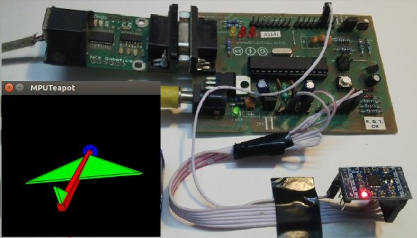
In this tutorial, I will give you a basic introduction to the MPU 6050, demonstrate how it can be interfaced to an Arduino, and show you how to make a 3D model using the data from your Arduino MPU 6050.
Required Materials
Hardware:
- Arduino or an Arduino clone board (Freeduino). Or make your own custom Arduino board with this tutorial.
- MPU 6050 sensor.
- Interconnecting wires.
Software:
- Arduino IDE: Arduino
- Processing IDE: Processing (optional)
How Does it Work?
IMU sensors usually consist of two or more parts. Listing them by priority, they are the accelerometer, gyroscope, magnetometer, and altimeter. The MPU 6050 is a 6 DOF (Degrees of Freedom) or a six-axis IMU sensor, which means that it gives six values as output. Three values from the accelerometer and three from the gyroscope. The MPU 6050 is a sensor based on MEMS (Micro Electro Mechanical Systems) technology. Both the accelerometer and the gyroscope are embedded inside a single chip. This chip uses I2C (Inter-Integrated Circuit) protocol for communication.
How Does an Accelerometer Work?
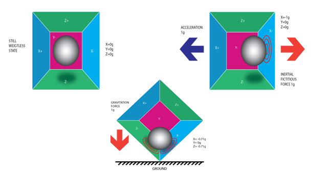
An accelerometer works on the principle of the piezoelectric effect. Here, imagine a cuboidal box with a small ball inside it, like in the picture above. The walls of this box are made with piezoelectric crystals. Whenever you tilt the box, the ball is forced to move in the direction of the inclination, due to gravity. The wall that the ball collides with creates tiny piezoelectric currents. There are three pairs of opposite walls in a cuboid. Each pair corresponds to an axis in 3D space: X, Y, and Z axes. Depending on the current produced from the piezoelectric walls, we can determine the direction of inclination and its magnitude.
How Does a Gyroscope Work?
Gyroscopes work on the principle of Coriolis acceleration. Imagine that there is a fork-like structure that is in a constant back and forth motion. It is held in place using piezoelectric crystals. Whenever you try to tilt this arrangement, the crystals experience a force in the direction of inclination. This is caused as a result of the inertia of the moving fork. The crystals thus produce a current in consensus with the piezoelectric effect, and this current is amplified. The values are then refined by the host microcontroller. Check this short video that explains how a MEMS gyroscope works.
Interfacing the Arduino MPU 6050
The MPU 6050 communicates with the Arduino through the I2C protocol. The MPU 6050 is connected to Arduino as shown in the following diagram. If your MPU 6050 module has a 5V pin, then you can connect it to your Arduino’s 5V pin. If not, you will have to connect it to the 3.3V pin. Next, the GND of the Arduino is connected to the GND of the MPU 6050.
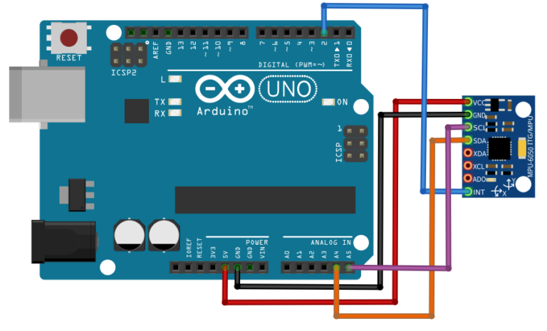
The program we will be running here, also takes advantage of the Arduino’s interrupt pin. Connect your Arduino’s digital pin 2 (interrupt pin 0) to the pin labeled as INT on the MPU 6050. Next, we need to set up the I2C lines. To do this, connect the pin labeled SDA on the MPU 6050 to the Arduino’s analog pin 4 (SDA) and the pin labeled as SCL on the MPU 6050 to the Arduino’s analog pin 5 (SCL). That’s it, you have finished wiring up the Arduino MPU 6050!
Uploading the Code and Testing the Arduino MPU 6050
To test the Arduino MPU 6050, first download the Arduino library for MPU 6050, developed by Jeff Rowberg. You can find the library here. Next, you have to unzip/extract this library and take the folder named “MPU6050” and paste it inside the Arduino’s “library” folder. To do this, go to the location where you have installed Arduino (Arduino –> libraries) and paste it inside the libraries folder. You might also have to do the same thing to install the I2Cdev library if you don’t already have it for your Arduino. Do the same procedure as above to install it, you can find the file here: I2Cdev library.
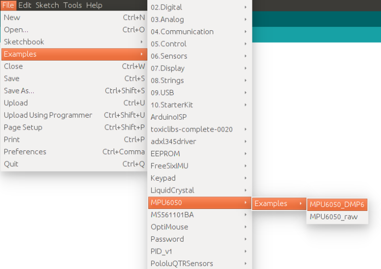
If you have done this correctly, when you open the Arduino IDE, you can see “MPU6050” in File –> Examples. Next, open the example program from: File –> Examples –> MPU6050 –> Examples –> MPU6050_DMP6.
Next, you have to upload this code to your Arduino. After uploading the code, open up the serial monitor and set the baud rate as 115200. Next, check if you see stuff like “Initializing I2C devices…” on the serial monitor. If you don’t, just press the reset button. Now, you’ll see a line saying “Send any character to begin DMP programming and demo.” Just type in any character on the serial monitor and send it and you should start seeing the yaw, pitch, and roll values coming in from the MPU 6050. Like so:
Next, you have to upload this code to your Arduino. After uploading the code, open up the serial monitor and set the baud rate as 115200. Next, check if you see stuff like “Initializing I2C devices…” on the serial monitor. If you don’t, just press the reset button. Now, you’ll see a line saying “Send any character to begin DMP programming and demo.” Just type in any character on the serial monitor and send it and you should start seeing the yaw, pitch, and roll values coming in from the MPU 6050. Like so:
Read More: IMU Interfacing Tutorial: Get started with Arduino and the MPU 6050 Sensor
- What are the primary applications of IMU sensors?
IMU sensors are used in self-balancing robots, UAVs, smartphones, and wearable gadgets like Fit Bit to detect orientation and track movement. - Which IMU sensor is considered the most reliable according to the article?
The Invensense MPU 6050 is identified as the most reliable and accurate IMU sensor available. - How does an accelerometer determine inclination?
An accelerometer uses the piezoelectric effect where a ball inside a box collides with walls made of crystals, creating currents that indicate direction and magnitude. - What protocol does the MPU 6050 use for communication?
The MPU 6050 uses the I2C (Inter-Integrated Circuit) protocol to communicate with the host microcontroller. - Which digital pin on the Arduino connects to the INT pin on the MPU 6050?
Digital pin 2, which serves as interrupt pin 0 on the Arduino, connects to the INT pin on the MPU 6050. - What baud rate should be set in the serial monitor for testing?
The baud rate must be set to 115200 when opening the serial monitor after uploading the code. - What output values can be expected from the MPU 6050?
The sensor provides six values including yaw, pitch, and roll derived from three axes of the accelerometer and gyroscope. - Where should the I2C library files be placed within the Arduino installation?
The library folders should be pasted inside the Arduino libraries folder located at the installation directory.