Summary of Hydrate Reminder
This article details the construction of an interactive hydration coaster that uses color-changing LEDs to remind users to drink water. The device employs a Force Sensitive Resistor (FSR) to detect when a cup is removed, resetting a timer that shifts LED colors from blue (hydrated) to red (dehydrated). The build process involves programming an Arduino Uno with FastLED libraries, designing and laser-cutting an acrylic plate, 3D printing a custom casing, and assembling all electronic components on a solderable breadboard.
Parts used in the Hydrate Reminder Coaster:
- 1x Arduino Uno
- 1x USB cable A - B
- 1x Breadboard
- 4x LED FastLed RGB diffuus through-hole WS2811 8mm
- 1x FSR 402 sensor
- 1x Prototype PCB Solderable Breadboard
- 1x 10kΩ Resistor
- 15x female to female end jumper wires
- 12x male to male end jumper wires
- Acryl plate (13 cm x 13 cm x 0.5 cm minimum)
- FDM filament (5m minimum)
An interactive coaster that reminds you to drink water.
I myself find it hard to reach the daily water intake. I can go on without water for hours when sitting behind my desk. For this purpose alsone, I created a coaster that reminds me to take a drink after a certain amount of time.
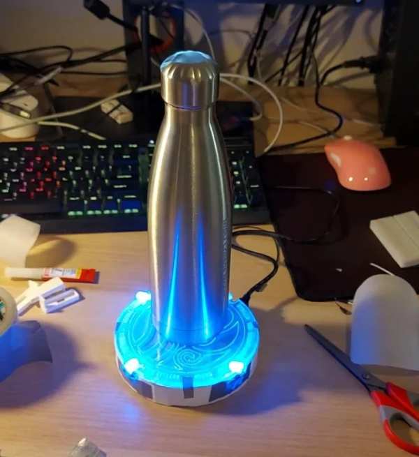
The coaster changes color depending on the last time you took a sip. From deep blue that represents the state of hydration to aggressive red that indicates desiccation. The color resets back to blue after a drink was taken.
Supplies
Hardware
1x Arduino Uno
1x USB cable A – B
1x Breadboard
4x LED FastLed RGB diffuus through-hole WS2811 8mm
1x FSR 402 sensor
1x Prototype PCB Solderable Breadboard
1x 10kΩ Resistor
15x female to female end jumper wires
12x male to male end jumper wires
*Depending on your wiring planning and soldering approach you might need less/more or different types of wire ends.
Acryl plate (13 cm x 13 cm x 0.5 cm minimum)
FDM filament (5m minimum)
Software
Arduino App
Blender or any other 3D modelling software like Maya
Cura (for 3D prinring)
Adobe Illustrator (or other illustration tool)
Additional Resources
A PC
3D printer
Lasercutter
Soldering iron
Solder tin
Paper
Baking paper
Scissors
Pencil
Circinus
Super glue
Painting tape
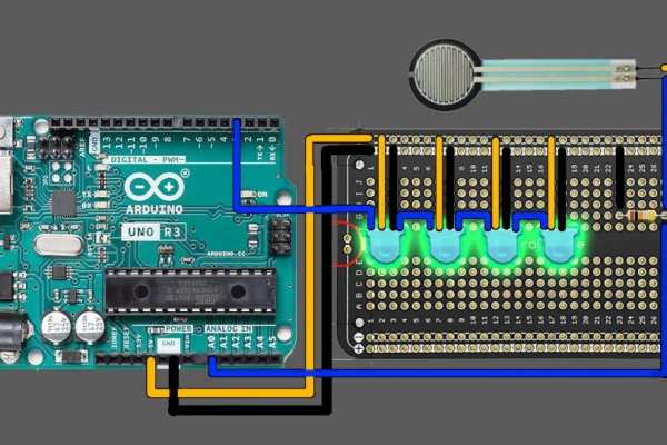
Step 1: Test Your LEDs
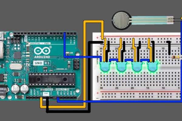
You should test your LEDs by attaching them to their corresponding outlets on the breadboard like in the example.
After connecting the circuit to you PC, run the Arduino App.
My LED’s were sold under the name “Adafruit NeoPixel“. After downloading the Adafruit library inside the Arduino App for test animation reels, nothing worked. Turns out the LED’s weren’t NeoPixels at all but FastLed!
Let’s download the FastLed library for the Arduino app
Arduino App > Sketch > Include Library > Manage Libraries
In the ‘Manage Libraries” window, type in “FastLed”. You should find a library called FastLED by Daniel Garcia. INSTALL IT!
Then you go to File > Examples > FastLED
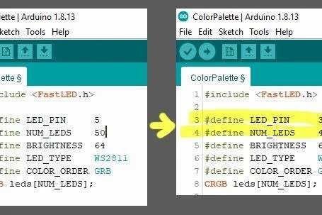
There you can choose from multiple lightning reels. In the example above, I used “Color Palette” to see how my LEDs react to all kinds of lightning effects.
Before running the code, you need to manually change the NUM_LEDS = your number of leds and the info LED_PIN = Output pin for the Arduino. In the video I tested with 6 LEDS but for the sake of the project you need just 4. Then you can upload the code into your Arduino and finally see some lights!
Step 2: Combine LEDs With FSR
The reason why we are using a FSR is that we will be using weight to determine of the water was drank or not. If the weight of the coaster won’t change within a certain time, the arduino will interpret that we haven’t drank and will change the colors of the LEDs. The FSR also causes the lights to turn on and off.
This step is based on this tutorial:
https://www.ardumotive.com/how-to-use-a-force-sensitive-resistor-en.html
Connect your FSR to the other side of the breadboard like shown above.
Step 3: The Code
Get the code for the coaster here:
The code shown above is a combination of the FastLED “pride2015” library and the FSR tutorial from the step prior.
FSR
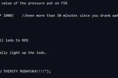
Row 66 of the code above represents the pressure value of the FSR. Mine is set to 150 with is the minimum value where my FSR doesn’t register itself on it’s own. Depending on the sensitivity of your FSR you might want to lower or increase that value so your light’s won’t get triggered by the sheer weight of FSR itself.
Lights
The code for the lights can be split in 6 parts:
- Rainbow – Colorful animation that indicates that the coaster had been turned on. The timer is reset to 0.
- Blue – Hydrated recently
- Green – Good level of hydration
- Yellow – Low level of hydration
- Red – Desiccation
- Black – The coaster is turned off (Absence of weight)
For testing purposes, I set the timer to change the colors every few seconds. When your lightning works as intended, feel free to increase the millisecond equation value of each color like shown in row 91. You can also very easily change the colors to your liking by simply replacing the name of your color with one from the #define COLOR_ORDER RGB
Step 4: Designing the Coaster
Now that you figured out the circuit and code, it’s time for the design part.
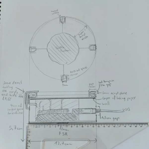
You will need a rough sketch of the entire construction. You’ll have to pay mind when it comes to the measurements of all the assets such as the arduino inside, placement and thickness of the LED’s, size of the acryl plate ect. I advise you to sketch on paper with a ruler so you get a good impression of how big your contraption will be.
My coaster has the diameter of 13cm. Depending on the side of your water bottle you might want to make the coaster bigger or smaller.
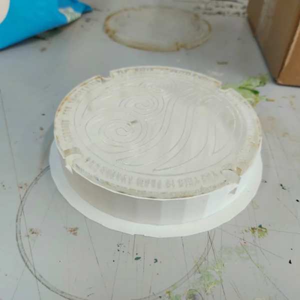
Step 5: The Acryl Plate
The acryl plate is necessary to display the light. When lit with LEDs, the engraved parts in the acryl light up and alert us of our hydration status.
The Design
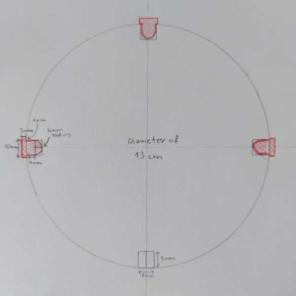
Create a round sketch on paper with a diameter that’s big enough for your water bottle and engraved markings around it. You need to make space for the LEDs and to do that, you need to cut an opening for each LED that follows the curvature of the light. If you’re using 8mm NeoPixels you can copy my led measurements for the design process.
Next open up Illustrator or a simmilar program and create a canvas/round object with the exact same resolution of your design. (My acryl plate has the diameter of 13cm so I created a circle of 13cm inside the program). You might want to change your default measurement units to mm to help with accuracy. Aim to re-create the pencil drawing.
Next you want to create a new layer for the engraved part. This part will light up! You can create any sort of linework. If you feel un-inspired like me, you can pick The Water Tribe logo like me. Make sure the design consists of only single color strokes. Every pixel seen in the area will be engraved, no matter the color, so keep transparency in mind.
I advise to engrave the edges since most part of your design will be covered by your water bottle.
Export
After you’re done with the deisgn, it’s time to export it as a .DXF file. You can open your .DXF file inside CURA or a similar program used for a lasercutter. Inside CURA, you can point out which part of the deisgn to cut and with part to engrave.
As for the lasercutter settings, each lasercutter is different. The thickness of your acryl plate plays a big factor in it. Check the instructions on your lasercutter for proper cut and engraving settings.
After lasercutting, check your acryl piece for any burn marks. Burn marks can be caused when too much power is used. You might also notice some some sticky dust covering your plate. You can simply wash it off.
You can use your acryl piece as a pattern for the baking paper that will cover the underside of your plate. Simply follow the shape of your acryl plate with a pencil on the baking paper and cut it out! The paper will help reflect the light upwards and will cover the wires & arduino underneath.
Step 6: 3D Casing
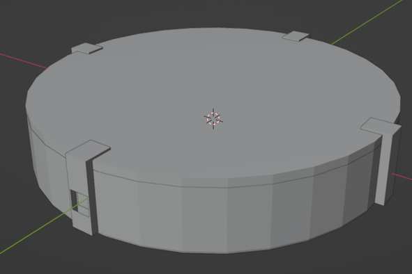
Now that you know how big your acryl plate is, you can choose the same diameter for the casing below. This is a model I created in Blender. I won’t provide you with the file for it because I messed up the scale and was forced to saw in it. I don’t want you to go through it so I encourage you to create your own model. Anyway, here are some tips that will help you create a better 3D model for the casing:
- Start by re-creating your acryl plate and the LED’s in 3D with exacty same measurements. This will help you to balance the rest of the measurements like minimum height to fit the arduino, cables and other items inside.
- Measure the height of your arduino + your entire circuit. You want to create enough space inside to fit everything neatly inside.
- Create a hole for the usb cable that reaches the arduino.
- Create a hole in the bottom for the neck of FSR to go through.
- Think of an opening-closing mechanism where it’s possible to easily take out the arduino if needed.
- Make all openings minimum of 2mm extra wide just to be sure everything falls into place when assembling.
- Create a thicker edge on the top of the coaster so the Acryl plate can sit ther ein place.
- DOUBLE CHECK THE MEASUREMENTS!
Export
You want to export your model as a .STL file.
Step 7: 3D Printing
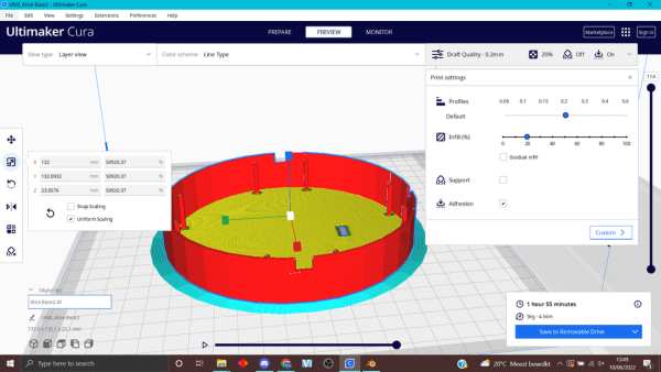
Open cura > File > New File > *here you can find your .STF file*
After you opened your 3D model in Cura, DOUBLE CHECK THE SCALE! In my case I had to re-size the entire scale of the file manually after opening my file.
Inside the program, you want to assign your 3D printer. Next you can go to the middle tab called “Preview” where you can play around with the print settings. Depending on your printer, available time and the filament you’re using, you might need to adjust it yourself.
After you’re done with the print, you’ll need to remove the excess/protective layer of plastic.
Step 8: Soldering
Prototype PCB Solderable Breadboard allows you to mimic your work from breadboard.
Soldering
Make sure you’re in a well ventilated space. We will be working with solder tin with lead and it’s fumes are very harmful once inhaled/in contact with your eyes.
Before you start soldering, you might want to strip some of your cables. If you’re using female to female end wires or male to female, you might not need to solder both ends onto the led legs but simply plug them in. Same for the FSR.
- Heat up your solder iron around 400 degrees Celcius.
- Flip the Prototype breadboard over
- Poke the stripped end of the wire through a hole in the board (double check by flipping the board over to see if you’re about to solder the wire into the correct place. (If it’s your first time soldering, you should follow a tutorial on how to solder because it takes practice)
- After soldering every single piece, attach the board in the arduino and run the code to see if it works or if there are any possible short circuits.
You might also want to manage your wires in some way. I taped together wires to each corresponding LED.
Step 9: Assembly
First check if your acryl plate fit’s neatly in the casing.
When it comes to assembling the components, you want to start with the pressure plate since it will be lodged on the very bottom. For now you can tape it down with double folded painter’s tape.
Then you want to place the breadboard and arduino contraption inside. Because my case was so small, I put the arduino on top of the empty space of breadboard. This is also a good time to shorten your wires if needed. Make sure to connect the USB cable to the arduino during this step.
Each led needs to fit inside the holes in the acryl plate. It’s possible to bend the legs of the LED in any way you want (Be aware that after too much wiggling they can break.) In my case I tucked them inside the case with the wiring and I taped them in place.
Then you can lay the baking paper cutout and shut everything with the acryl plate. You can secure the construction by taping the edges unless you developed a closing/opening structure.
Step 10: Test Your Coaster!
Source: Hydrate Reminder
- How do I determine if my LEDs are NeoPixels or FastLED?
The author found that LEDs sold as Adafruit NeoPixels were actually FastLED compatible, requiring the installation of the FastLED library instead of the Adafruit library. - What role does the FSR 402 sensor play in this project?
The FSR uses weight detection to determine if water has been drunk; it also triggers the lights to turn on and off based on pressure changes. - What color indicates that the user is dehydrated?
The aggressive red color indicates desiccation, while deep blue represents the state of hydration. - How can I adjust the sensitivity of the FSR sensor?
You can modify the pressure value in row 66 of the code to match your specific sensor's minimum threshold to prevent false triggering. - What software is required to design the acrylic plate?
Adobe Illustrator or similar illustration tools are needed to create the vector design which is then exported as a .DXF file for the lasercutter. - Why is baking paper used under the acrylic plate?
The baking paper reflects light upwards and covers the wires and Arduino underneath the plate. - What settings should be checked before exporting the 3D model?
You must double-check the scale and ensure measurements for the Arduino, cables, and LED openings are accurate before exporting as a .STL file. - What safety precautions are necessary during soldering?
Soldering should be performed in a well-ventilated space because solder tin fumes containing lead are harmful if inhaled or contacted by eyes.