Summary of How to Use Water Flow Sensor – Arduino Tutorial
Summary: This tutorial explains using a water flow sensor with an Arduino to measure flow rate and total volume. The sensor uses a rotor and Hall-effect sensor to output pulses proportional to flow. The guide lists required parts, shows simple wiring to the Arduino, and provides code (via Codebender) to print liters per hour and cumulative liters to the serial monitor. It notes sensor specs vary and suggests selecting an appropriate diameter, pressure, and flow range.
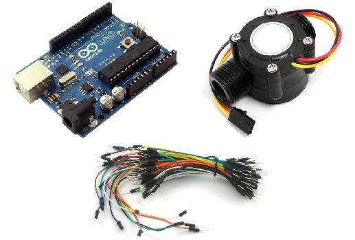
Parts used in the Water Flow Sensor with Arduino Project:
- Arduino Uno
- Water flow sensor (20mm diameter, <1.75 MPa, ~30 L/m sensor example)
- Breadboard jumper cables (3)
In this tutorial you will learn how to use one water flow sensor with an Arduino board.
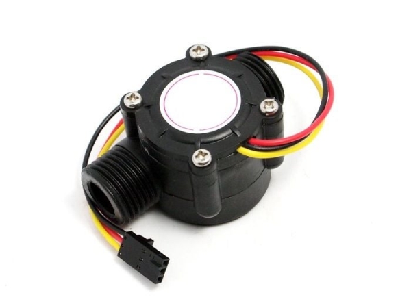
The water flow sensor consists of a plastic valve body, a water rotor and a hall-effect sensor. When the water flows through the rotor, rotor rolls and the speed of it changes with a different rate of flow. The hall-effect sensor outputs the corresponding pulse signal.
This type of sensor can be found on different diameters, water pressure (MPa) and flow rate (L/m) ranges. Make sure to select one that will cover your needs. The sensor that I have it has 20mm diameter, <1.75Mpa water pressure and ~30 L/m flow rate range.
In this tutorial we will use the serial monitor for printing the water flow rate in liters per hour and the total of liters flowed since starting.
So let’s get started!
Step 1: What You Will Need
For this tutorial you will need:
- Arduino uno
- Water flow sensor
- 3 breadboard cables
Step 2: The Circuit
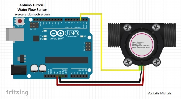
The connections are pretty easy, see the above image with the breadboard circuit schematic.
Step 3: The Code
Here’s the code, embedded using Codebender!
Try downloading the Codebender plugin and clicking on the “Run on Arduino” button to program your Arduino board with this sketch. And that’s it, you’ve programmed your Arduino with this sketch!
You can keep playing with that by clicking the “Edit” button and start making your own modifications to the code. For example you can change in the line 58 the “1000” ms delay time.
Read more: How to Use Water Flow Sensor – Arduino Tutorial
- What does the water flow sensor consist of?
The sensor consists of a plastic valve body, a water rotor and a hall-effect sensor. - How does the sensor output relate to water flow?
The rotor spins as water flows and the hall-effect sensor outputs pulse signals with a rate proportional to flow. - What Arduino board is used in the tutorial?
An Arduino Uno is used in the tutorial. - What does the tutorial print to the serial monitor?
It prints the water flow rate in liters per hour and the total liters flowed since starting. - How many jumper cables are listed as needed?
Three breadboard jumper cables are listed. - Where is the example code provided?
The code is embedded using Codebender and can be loaded via the Run on Arduino button. - Can you modify the code delay time?
Yes, the tutorial mentions changing the 1000 ms delay time in line 58 as an example. - What sensor specifications should you consider when selecting one?
Select a sensor with appropriate diameter, maximum water pressure (MPa), and flow rate (L/m) ranges for your needs.