Summary of How to use a while loop to calibrate the value of an analog sensor using Arduino
This article explains how to use a `while` loop in an Arduino sketch to calibrate an analog sensor. When a button is pressed, the program enters a calibration routine that records the sensor's minimum and maximum values based on current conditions. Once the button is released, the main loop resumes, using these calibrated values to control an LED's brightness. This method allows dynamic adjustment of sensor thresholds as lighting changes.
Parts used in the While Loop Sensor Calibration Project:
- Arduino Board
- Digital pushbutton or switch
- Photocell or analog sensor
- 10K ohm resistors (2)
- 220 ohm resistor
- Breadboard
Sometimes you want everything in the program to stop while a given condition is true. You can do this using a while loop. This example shows how to use a while loop to calibrate the value of an analog sensor.
In the main loop, the sketch below reads the value of a photoresistor on analog pin 0 and uses it to fade an LED on pin 9. But while a button attached to digital pin 2 is pressed, the program runs a method called calibrate() that looks for the highest and lowest values of the analog sensor. When you release the button, the sketch continues with the main loop.
This technique lets you update the maximum and minimum values for the photoresistor when the lighting conditions change.
Circuit
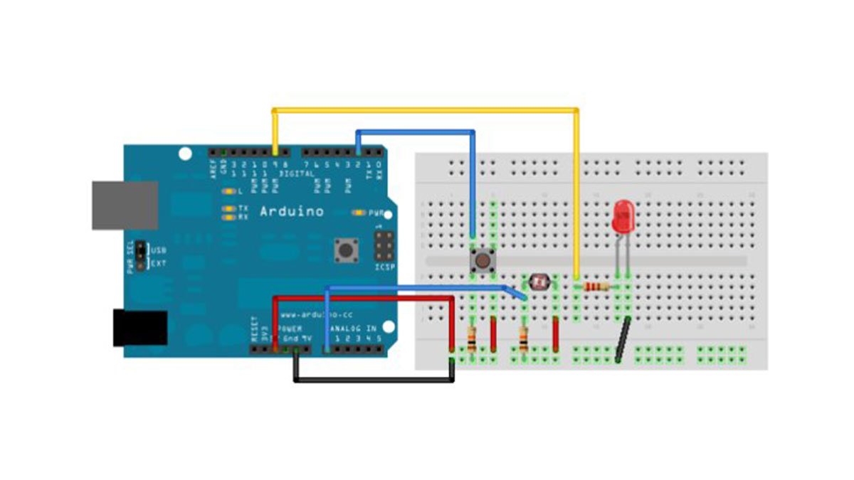
Connect your analog sensor (e.g. potentiometer, light sensor) on analog input 2 with a 10K ohm resistor to ground. Connect your button to digital pin, again with a 10K ohm resistor to ground. Connect your LED to digital pin 9, with a 220 ohm resistor in series.
image developed using Fritzing. For more circuit examples, see the Fritzing project page
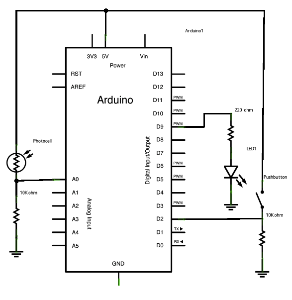
Schematic:
Code
Conditionals – while statement
This example demonstrates the use of while() statements.
While the pushbutton is pressed, the sketch runs the calibration routine.
The sensor readings during the while loop define the minimum and maximum
of expected values from the photo resistor.
This is a variation on the calibrate example.
The circuit:
* photo resistor connected from +5V to analog in pin 0
* 10K resistor connected from ground to analog in pin 0
* LED connected from digital pin 9 to ground through 220 ohm resistor
* pushbutton attached from pin 2 to +5V
* 10K resistor attached from pin 2 to ground
created 17 Jan 2009
modified 30 Aug 2011
by Tom Igoe
Hardware Required
- Arduino Board
- (1) digital pushbutton or switch
- (1) photocell, or analog sensor
- (2) 10k ohm resistors
- breadboard
- How does the program behave when the button is pressed?
The program runs a method called calibrate that looks for the highest and lowest values of the analog sensor. - What happens after the button is released?
The sketch continues with the main loop. - Which pin is used for the photoresistor?
The photoresistor is connected to analog pin 0. - Where is the LED connected?
The LED is connected to digital pin 9 with a 220 ohm resistor in series. - What is the purpose of the while loop in this project?
The while loop is used to stop other program actions while calibrating the value of an analog sensor. - Can you update the maximum and minimum values for the photoresistor?
Yes, this technique lets you update the maximum and minimum values when lighting conditions change. - How many 10K ohm resistors are required?
You need two 10K ohm resistors for the circuit. - What component is attached to digital pin 2?
A pushbutton is attached to digital pin 2.