My brother posted a video about this on facebook almost a year ago. Some old floppy drives playing Bach’s masterpiece Toccata & Fugue and it got me really interested. So I read about it when the author posted a how-to on his blog and did a couple of tweaking using SammyIAm’s Musical Floppy program when the project gained a lot of attention.
WHAT YOU NEED
1) Arduino – Ideally, you need the Arduino UNO but any Arduino would work. You just need to tweak something in the program with the pin assignments. In this mini-project however, I used Duemilanove. It works almost accurately as Arduino UNO and I didn’t have to tweak anything.
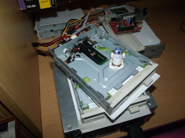
2) Floppy Drives/Disks – Any floppy drive would work but it’s a lot easier to use the 34-pin simply because it’s common. Other than that, you would only be needing to determine 3 pins from your floppy. Pin assignments are available online, particularly here. Furthermore, I was trying to acquire a 5.25 floppy drive but to no avail, and ebay sells them around $20 so I said never mind about that. As a result, this project is composed only of the 3.25 floppy disk drives. You also need some floppy diskettes for this project.
3) Power Supply – Again, it depends on you. You can use any 5-volt power supply available but since an ATX power supply is just lying around at home, I conveniently used it instead.
4) CAT5 UTP Cable – Only because of the wires. I want my wires to be color-coded.
5) Breadboard – If you want a solderless-free project.
6) Soldering Iron/Lead – For soldering the pins you would need to connect your CAT5 UTP cable to, but if you still have the flat ribbon cable then good for you. Might as well use that to make it easier.
7) Cutter, Phillips/Flathead screwdrivers – For dismantling purposes.
Step 1: Prepare your power supply.
Again, it depends on you. You can use any 5-volt power supply available but since an ATX power supply is just lying around the house, it would be pretty convenient to use it here. However, if you just have the power supply (without a motherboard), to activate it you need to short two wires, BLACK andGREEN as shown on the image. Connect these two wires and your power supply is then activated.
Step 2: Determine the needed pins for your floppy drives.
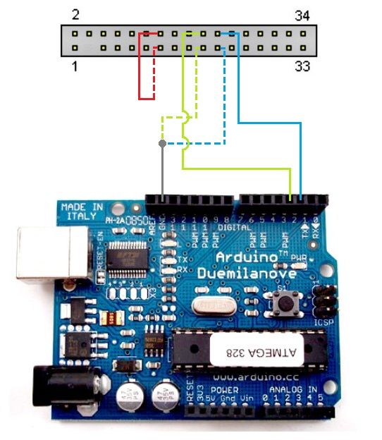
Like what I said earlier, you only need to determine 3 pins to make the floppy drive sing. If you look at the back of your floppy drive you would see these 34 pins. Just check on the image to determine which is pin 1 and so on. The top pins are the even pins the bottom pins are the odd pins which is the ground. The even-numbered pins are activated by grounding them. Basically, computers have up to two floppy drives A and B. Doesn’t really matter which drive you connect your wires to. If you want to set your floppy drive to drive B, then connect wires to pins 12, 11 for the ground. If you want to set your floppy drive to drive A, then connect wires to pins 14, 13 for the ground. But to avoid further complications, just select drive B, pin 12 and 11.
Another pin that we are interested in is the direction pin 18, 17 for the ground. Direction pin determines which direction to move, forward or backward. This movement is actually the one causing the low-note and high-note sound coming out of the floppy drive.
Finally, the last pins we need to connect wires to is the step pin 20, 19 for the ground which basically activates the stepper motor to move.
NOTE: If you still have the flat ribbon cable then I suggest that you use it instead of soldering wires directly to the pins of your floppy drive. Soldering them could fry the boards of your floppy but since I don’t have any flat ribbon cables and connector I soldered mine. Solder at your own risk.
Step 3: Test your floppy drives.
Connect your floppy to your power supply and test the stepper motor. Notice that if you connect your floppy drive to the power supply nothing is happening, that is because you need to connect pins 11 and 12 to activate it. To activate your floppy, you need to permanently connect the drive select pins 11 and 12, so you can go on twist those wires or solder them. You can easily determine if you have the wires connected. Once you connect the wires attached to pins 11 and 12, the light of the floppy drive should turn on.
Next thing you need to do is check on the direction and step pins. Connecting the green wires together pins 17 and 18 would make your stepper move forward. To activate the stepper motor you just need to tap the blue wires which is connected to the step pins. Moving the stepper motor backward, all you need to do is disconnect your green wires then activate your stepper by tapping the blue wires.
2) Floppy Drives/Disks
3) Power Supply
4) CAT5 UTP Cable
5) Breadboard
6) Soldering Iron/Lead
7) Cutter, Phillips/Flathead screwdrivers
For more detail: How to Make Musical Floppy Drives using an Arduino