
Summary of How to Make a Garage Door (EASY!!!)
This article details an easy Arduino project to build an IR sensor-controlled garage door using two servo motors. The system detects signals from a standard TV remote via an infrared receiver to open and close the door, with optional LED lighting for visual feedback. It includes step-by-step instructions for research, wiring components like servos and sensors, uploading C++ code, and assembling a physical frame from wood or 3D printing materials.
Parts used in the IR Sensor-Controlled Garage Door:
- 2 Servo Motors
- 1 Infrared Sensor (IR)
- 1 Infrared Remote (TV remote)
- 2 Resistors
- 5-10 LEDs
- 1 Breadboard
- 1 Arduino Uno
- Frame (wood or 3D printed)
- Construction Paper
- Wire Cutter
- Glue Gun
- Soldering Iron
- Wires
- 2 9v Batteries
- 1 Battery cap (buckle connector)
- 1 Battery cap (male DC plug)
This is a EASY arduino project that you could create to impress your teacher and friends. This project is an IR sensor-controlled garage door. It uses 2 Servo motor’s to move the garage door into an opened and closed orentation. The inferred sensor (IR) is effective and long range with a range of 1-5 meters. This project is great When paired with an arduino car project.
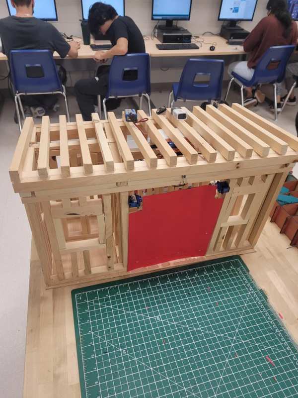
Supplies
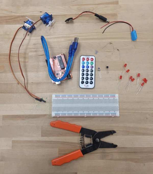
Electronics:
- 2 Servo Motor’s
- 1 Infarred Sensor (IR)
- 1 Infarred Remote (IR) (any tv remote works)
- 2 Resistors
- 5-10 LED’s (optional)
- 1 Breadboard
- 1 Arduino Uno
Accessories:
- Frame (wood, 3D printed)
- Construction Paper (Garage door)
Tools:
Power/Connections:
Step 1: Research
There was a planning process before I started this project to figure out what to do. I wanted to create something unique that had never been done before, and I couldn’t find anything on garage doors. So, right there, I confirmed my project idea. This section contains background information on the most important and intricate components.
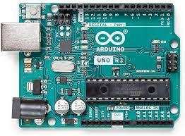
Arduino:
- Arduino is an open-source electronics platform that uses simple hardware and software to make it easy to use. Arduino boards can take inputs – such as light from a sensor, a finger on a button, or a Twitter message – and convert them to outputs – such as turning on an LED, triggering a motor, or publishing anything online. The arduino uses the format code of C++.
Infarred Receiver (IR):
- IR(Infrared) Receiver Extender cable, which consists of an IR receiver and a plug connected by a wire, is used to conveniently receive and amplify the infrared remote controller signal. The epoxy package and shell of an infrared receiver can filter out visual interference.
Servo Motor:
- A servomotor (or servo motor) is a rotary actuator or linear actuator that can control angular or linear position, velocity, and acceleration precisely. It consists of a suitable motor coupled to a position feedback sensor.
Transistor (NPN):
- The NPN transistor is designed to pass electrons from the emitter to the collector (so conventional current flows from collector to emitter). The emitter “emits” electrons into the base, which controls the number of electrons the emitter emits.
Step 2: Wiring Part 1
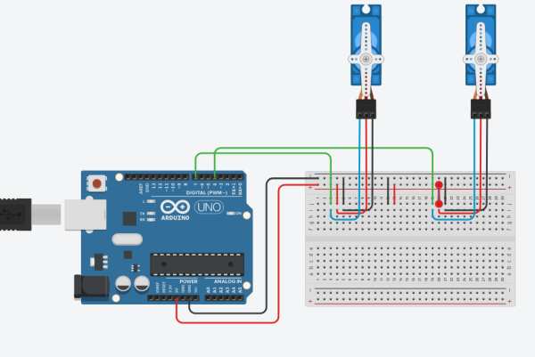
Before Starting the wiring let me tell you what each wire color represents:
Black = Ground
Red = Power
Green = Arduino Output To BredBoard
Blue = Arduino Output To Component
Steps:
- Connect power and ground from the arduino to the bredboard
- Connect the first servo to pin 11 on the arduino
- Connect the second servo to pin 3 on the arduino
Note : connecting the servos to the arduino will allow it to send code straight to the servo
Step 3: Wiring Part 2
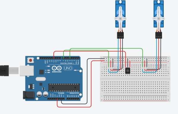
In this wiring step, we will connect the IR receiver. The IR Reciver is the most important component in this project because it connects to a controller, which sends signals to the arduino and then to the servo to tell it to move up and down when pressed.
Steps:
- Connect the IR Reciver to pin 7 on the arduino
- connect the IR Reciver to Power and Ground
Note : For the IR Controller you will program that in the coding section. also make sure that the IR reciver in facing in the downwards direction of the bredboard
Step 4: Wiring Part 3 (optional)
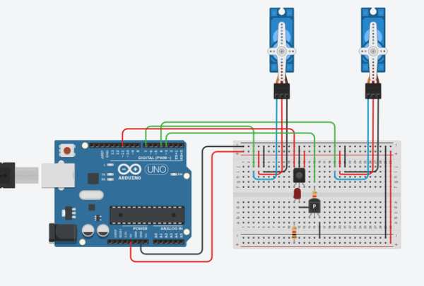
This step is optional; it simply adds a spark to the project by turning on a light when the garage opens and off when the garage closes. Instead of just one led, I soldered eight together to make a chandalier. Looking at the diagram, the inner circle connects to ground, while the outer circle connects to power.
Steps:
- Connect Arduino pin 4 to the transistor’s base (make sure the connection is through a 1k OHM resistor)
- Connect the LED’s negative side to the emitter and positive side to power from the bredboard (make sure poweris connected thorugh a 330 OHM resistor)
- Connect the transistor’s collector side to ground directly.
Step 5: Code
Simply copy and paste the code into the Arduino editor and connect your computer to the Arduino to upload it. To program your remote controller with your IR just open up the serial monitor then click the button you want to be assigned to that command e.g. if your want 1 to be forward click 1 on your remote while pointing it at the IR then look for the Hexacode that pops up and copy that into “if (results.value == 0x000000)” keep the 0x but replace the other long string of numbers and letters with your Hexacode.
#include <IRremote.h>
#include <Servo.h>
int IRpin = 7;  // pin for the IR sensor
IRrecv irrecv(IRpin);
decode_results results;
Servo myservo, myservo2;
int ledChan = 4;
void setup()
{
 pinMode(ledChan,OUTPUT);
 Serial.begin(9600);
 irrecv.enableIRIn(); // Start the receiver
 myservo.attach(11);  // attaches the servo on pin 9 to the servo object
 myservo2.attach(3); // attaches other servo
}
void loop()
{
 if (irrecv.decode(&results))
   {
    Serial.println(results.value, HEX);
     irrecv.resume();   // Receive the next value
   }
  if (results.value == 0xC1AAFC03)  // change according to your IR remote button number
    {
      myservo.write(190);
      myservo2.write(90);
      digitalWrite(ledChan, LOW);
      delay(15);
    }
    if (results.value == 0xC1AAC43B)  // change according  to your IR remote button number
   {
      myservo.write(90);
      myservo2.write(190);
      digitalWrite(ledChan, HIGH);
      delay(15);
    }

}
Step 6: Frame Assembly
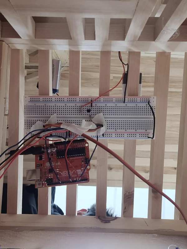
When all of the wiring and code is finished, it’s time for the final assembly. I used a small immatation of a house that I had lying around for the frame. I cut a hole in one of the walls that I thought was big enough for the garage door. If you don’t have the materials, don’t worry; you can make a frame out of whatever you have lying around; just make sure it has a rectangular shape to which you can glue the servos.
Steps :
- Glue the bredboard and arduino to the inner-top of the frame
- glue the servos to either side of the frame, facing eachother
- cut out a peice of construction paper that fits the dimensions of the frame and glue to the arms of the servo
Note: if the servos are opening in the opposite directions, Flip one of them . also make sure the IR Reciver is visible and not behind something
Step 7: Conclusion
If you followed the steps correctly, you should have a fully functional garage door. If not, go over the steps again to see where you went wrong. The video attached i what it should look like when working.
Source: How to Make a Garage Door (EASY!!!)
- How do I program my remote controller?
Open the serial monitor, click the button you want to assign, find the Hexcode that pops up, and replace the string in the code while keeping the 0x prefix. - Can I use any TV remote for this project?
Yes, the article states that any TV remote works as an infrared remote for this project. - What is the effective range of the IR sensor?
The IR sensor is effective and long-range with a range of 1-5 meters. - Which pins on the Arduino are used for the servos?
The first servo connects to pin 11 and the second servo connects to pin 3. - Does the IR receiver need to face a specific direction?
Yes, the IR receiver must be facing downwards towards the breadboard. - What happens if the servos open in opposite directions?
You should flip one of the servos to correct the orientation. - How do I add lights to the garage door project?
Connect Arduino pin 4 to a transistor base through a 1k resistor and connect LEDs to power and ground with a 330 ohm resistor. - What material can be used for the garage door?
Construction paper cut to fit the frame dimensions can be glued to the arms of the servo.
