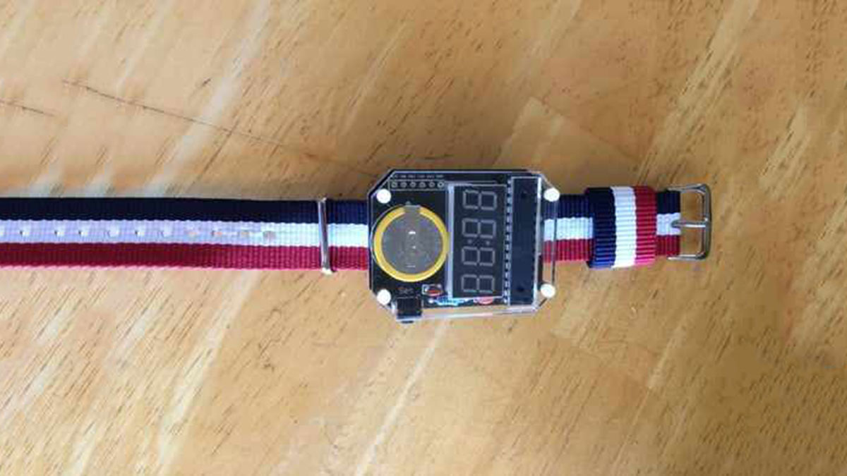
Summary of How to Make a Digital Watch
This Instructable describes building a digital watch from a SainSmart kit by soldering components onto a PCB and assembling an acrylic enclosure and band. The steps cover organizing parts and tools, then soldering the resistor, 32 kHz crystal, ATmega328 DIP socket, 4-digit display, and two 0.1 µF capacitors, with tips on orientation and solder technique.
Parts used in the Digital Watch:
- Pre-programmed ATmega328 DIP IC
- 28 pin DIP IC base (socket)
- 4-digit display
- 32 kHz crystal
- 10 kOhm resistor
- Two 0.1 uF capacitors
- Right angle tactile button
- 20 mm coin cell battery with battery holder
- Four M2*7 mm screws
- Four threaded brass M2*7 mm (nuts/inserts)
- Nylon watch band
- Acrylic enclosure parts
This is the first time I am writing an Instructable so hopefully I write well enough for you to understand. Today I will be telling you how to make a digital watch from a website that I found. The website is called sainsmart.com. It was really easy except for one time when I put on too much solder, so have fun and don’t put on too much solder!
Step 1: Organize the Components of the Watch and the Equipment Needed
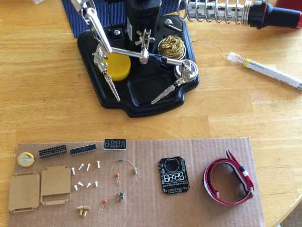
Components of the watch:
One Pre-programmed ATMega328 DIP IC
One 28 pin DIP IC base
One 4-digit display
One 32kHz crystal
One 10kOhm resistor
Two 0.1uF capacitors
One right angle tactile button
One 20mm coin cell battery with battery holder
Four screws M2*7mm
Four threaded brass M2*7mm
One nylon watch band
Acrylic enclosure parts
Equipment:
Soldering iron
Solder
Copper wick
2mm screwdriver
wire cutters
Step 2: Soldering the Resistor
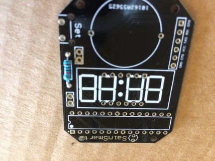
It is always easier to put the smallest parts in first, so start with the resistor. Put the resistor in, so the legs of the resistor are on the side without the numbers and letters. Bend the legs so that it is easier to solder on without having to hold the resistor. Solder it to the board and then use the wire cutters to cut off the bent legs of the resistor. It is ok if some of the solder went to the other side of the board, it helps it to stay together.
Step 3: Soldering the Crystal
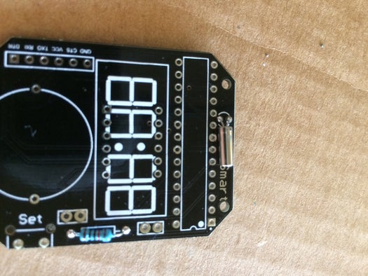
When you solder in the crystal it is a bit different. You will want the crystal to be parallel to the board, so bend the legs so that when you fit the legs in, the crystal is parallel to the board. Then solder the crystal on. You want a nice joint to hold it together so be careful that you don’t put on too little or too much solder.
Step 4: Soldering the Base of the Chip
You need to be careful when you solder in the base. There is a certain way that you have to solder it in. There is a semicircle on the board that matches a semicircle on the base. Fit the semicircle of the base onto the semicircle of the board. Then you can solder it on. You should start soldering at one end and then you go to the opposite end so that it stays in the board without holding it. Then you work your way in the same way.
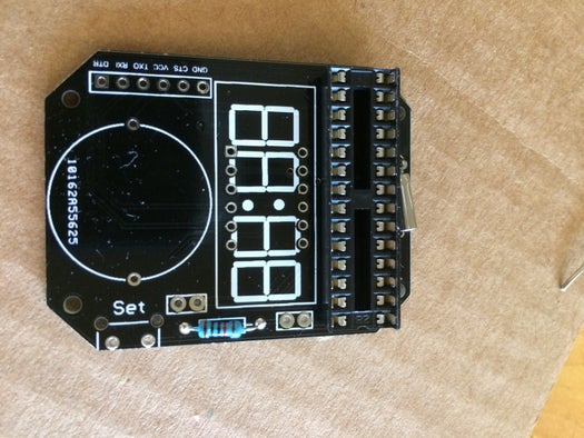
Step 5: Soldering the 4 Digit Display
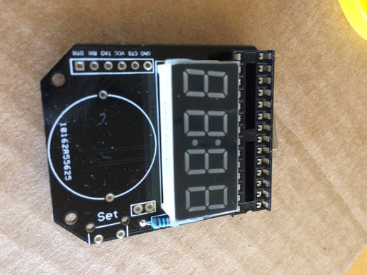
There is a certain way that you have to put in the display. If you look at one of the longer sides there are letters. Make sure the letters are facing where the battery will be, in other words the circle on the board. Solder the display on like how you soldered on the base for the chip. Start soldering on one end and move to the other end and vice versa.
Step 6: Soldering the Capacitors
The capacitors are the next thing you should put in. There is no significant way for the capacitors to go in, so you can just put it in any way. When you put it in, bend the legs of the capacitors so that its easier to solder in. Once soldered, cut off the legs of the capacitors.
Source: How to Make a Digital Watch
- What is the first step in building the watch?
Organize the components of the watch and the equipment needed. - How should the resistor be placed?
Put the resistor so the legs are on the side without the numbers and letters, bend the legs, solder, then cut off the legs. - How should the 32 kHz crystal be oriented when soldering?
Bend the legs so the crystal sits parallel to the board, then solder it with a clean joint. - How do you align the DIP IC base on the board?
Match the semicircle on the base to the semicircle on the board, start soldering at one end and the opposite end, then work inward. - How should the 4-digit display be oriented?
Ensure the letters on the longer side face where the battery will be (the circle on the board), then solder starting at one end and move to the other. - Is there a specific polarity for the 0.1 uF capacitors?
No; the capacitors have no significant orientation, so they can be placed in any way, then soldered and trimmed. - What tool is recommended if too much solder is applied?
Copper wick is listed among the equipment and can be used to remove excess solder. - What should you avoid when soldering?
Avoid applying too much solder, as the author experienced a problem with excess solder.