I’m a huge fan of technology and music, but when I decided to start making my own electronic music, I was discouraged by the high price of MIDI keyboards and controllers. After a lot of tinkering, I saw the opportunity to create my own MIDI keyboard using an Arduino Uno and electric paint, for a fraction of the price compared to existing MIDI devices!
In this tutorial, I will explain and show you how to create your own cheap MIDI controller using an Arduino and electric paint. I will show you step-by-step instructions on how to make the prototype board, how to flash your Arduino with the right software and how to connect and use it with electric paint. In the end, you will have build your own MIDI controller with 12 keys, which has the ability to change octaves and has a Control Change Parameter which responds to the height of your hand above the controller. Let’s get started!
Step 1: Gathering Materials
Apart from the electric paint and the actual Arduino Uno board, I was able to get all the electronic parts at a local shop in the Netherlands for €3,50. I did my best to link the parts I used in the Amazon store, but by searching for the parts in your own local electronic (internet) shop, you can lower the price significantly.
Also, If you can’t find the exact components I used, you should be able to make reasonable substitutions and the MIDI controller should still work (e.g. you could use a slightly different resistor values or leave certain sensors out).
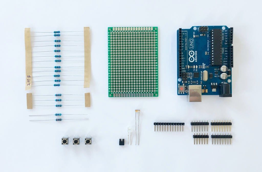
For the electronics, you will need the following:
1 Arduino Uno with an usb cable
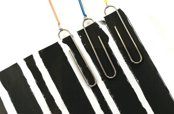
1 jar of Electric Paint
1 5x7cm prototype PCB board
3 pushbuttons with matching 2.2K ohm resistors
1 LED with a matching 10K ohm resistor
1 LDR sensor with a matching 4.7K ohm resistor
1 mini jumper connector
12 2.7M ohm resistors (2.700.000 ohm)
30 straight male pin headers
12 bended male pin headers
12 male-to-female jumper wires
12 uncoated paperclips
Besides the nessecary electronics, the following tools may also come in handy:
Soldering iron and solder
A wire stripper
A side cutter
A third hand soldering stand
A multimeter
Some extra wires and/ or thin iron wire
In the following 7 steps, we are going to make a prototype board which can be placed on the Arduino Uno. This will be used as a simple interface to connect the electric paint and to modify certain MIDI settings.
NOTE: During the remainder of this Instructable, I will refer to the prototype board as PCB.
Step 2: Soldering the Headers
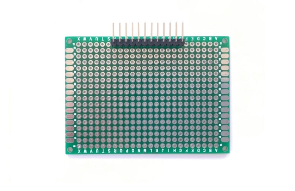
The first step of creating the PCB begins with soldering the headers in the right place. Start by placing the 90° bended headers in the center of the first row on the PCB board, as seen in the first image. These pins will later act as touch sensitive pins to which you can connect the electric paint.
After inserting the headers in to the PCB slots, you might notice that the pins stick out on the bottom of the PCB. To solve this, push them back a little, while firmly pressing the black plastic guiders to the PCB. This ensures the pins are flush with the PCB. Now solder the pins from the bottom of the PCB and make sure no connections touch each other.
NOTE: Do not apply too much heat for too long on the pins, otherwise they get very hot and melt the plastic.
For the second step, place all the straight headers into the slots on your Arduino, like in the second image. Now for the tricky part, place the PCB on the headers inserted in to the Arduino. You might notice that this action requires a little bit of force and that the pins do not align perfectly in the slots of the PCB, as seen in the third image. Unfortunately, Arduinos are not designed with the use of PCBs in mind, but there is nothing we can do about it 😉
After you succeeded putting the PCB on the headers, make sure the pins are flush with the top of the PCB and solder them from above. Now you should have a nice prototype board which can be placed on and be taken of the Arduino Uno.
Step 3: Soldering the Pads/ Traces
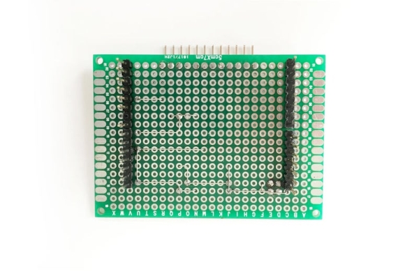
Now remove the PCB from your Arduino and flip it on its back, like in the first image. In this step we are going to make pads/ traces to which we can later add components. There are two ways of doing this:
- Fill in all the needed holes with solder to form a trace and connect them to each other
- Make use of thin (iron) wire
I advise using the second method, since it is easier and quicker to do. If you choose this method, follow the layout of the wires on the PCB in the second image. A red dot means you should solder the wire on that spot. A yellow dot means that you should connect the thin wire to the headers on the other side of the PCB, like in the third image. (As you can see, I messed up a little on the lower left corner of the PCB when applying to much solder, be careful with that!)
TIP: If you don not have any thin wire, cut the legs of some used resistors to use them as traces!
Read more: How to Make a Cheap Arduino MIDI Controller