Summary of How to Add an E-Ink Display to Your Project
This article details integrating an E-Ink display with an Arduino for low-power data monitoring, such as tracking salt levels in a water softener. It compares display types, selects the E-Ink model for its memory retention and energy efficiency, and provides step-by-step instructions for hardware connections, software library installation (vendor and enhanced), and custom programming to draw text and graphics on the screen.
Parts used in the E-Ink Display Project:
- E-Ink display module (1.54" 4-wire SPI version)
- Arduino board (Uno, Pro Mini, Pro Micro, or Nano)
- 9V lithium smoke detector battery
- SPI patch cable (8-way)
- USB cable
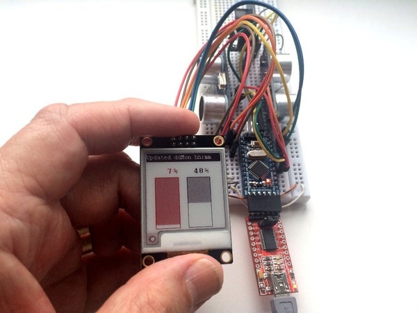
Lots of projects involve monitoring of some kind of data, such as environmental data, often using an Arduino for control. In my case, I wanted to monitor the salt level in my water softener. You might want to access the data over your home network, but equally you might want to display it where it’s being measured. Or you could have an always-on remotely connected display in a more convenient location.
There are now several kinds of display you can use, all quite cheap, but having different advantages and disadvantages:
- An alphanumeric LCD display is the cheapest but also the most limited.
- An OLED display can display graphics but the cheap ones are very small. The second photo shows a 128×64 pixel OLED display next to an E-Ink one.
- An E-Ink (or E-Paper) display is somewhat larger and hence easier to read, and has the advantage that the display is retained even when it’s switched off! But it takes several seconds to redraw the display.
The E-Ink display seemed ideal for my application as I could program the Arduino to wake up only every few hours, take a reading and display it before going back to sleep. It’s then of no consequence that it takes several seconds to redraw the display.
In such an application, the average current consumption can be arranged to be so low that a 9V lithium smoke detector battery can be made to last for 10 years! What’s more, some of these displays will display three colors: white, black, and red (or yellow). Ideal if you’d like to display a warning or alert in red.
Supplies
The cheapest E-Ink displays I’ve found are sold by BuyDisplay, also available from many eBay sellers. Unfortunately the documentation leaves quite a lot to be desired so I took it upon myself to write a tutorial – read on!
Depending on your requirements and your budget, you have the choice of various sizes:
- 1.54″ (152×152 = 23,104 pixels)
- 2.13″ (212×104 = 22,048 pixels)
- 2.6″ (296×152 = 44,992 pixels)
- 2.7″ (176×264 = 46,464 pixels)
- 2.9″ (296×128 = 37,888 pixels)
- 4.2″ (400×300 = 120,000 pixels)
- 5.83″(640×480 = 307,200 pixels)
- 7.5″ (880×528 = 464,640 pixels)
(The range has exanded since last time I looked so may have expanded further by th time you read this.)
They are available as either 2-colour (black/white) or 3 colour (black/red/white or black/yellow/white). This Instructable assumes you are using the red one, but if you have chosen the yellow version, simply read “yellow” for “red” throughout.
Choose an SPI (4-wire) version. I used the 1.54″ model, which is a very nice size.
Step 1: Connecting Your Display
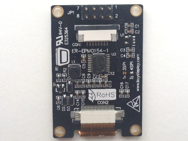
These displays come with a 2×4 pin header. The pin numbers are clearly labelled, pins 7, 5, 3 and 1 (from left to right) along the top row and 8, 6, 4, 2 along the bottom.
Your display may come with an 8-way patch cable, which makes connection easy. (My patch cable has 2 red wires and 2 brown. They are not interchangeable!
The following table gives the connections, which apply to most types of Arduino (including Uno, Pro Mini, Pro Micro and Nano).
| E-ink Module | Arduino | ||
| Pin | Name | Pin | Name |
| 1 | VDD | Vcc | 3.3/5V |
| 2 | VSS | Gnd | Gnd |
| 3 | Serial Data In | 11 | MOSI |
| 4 | Serial Clock In | 13 | SCK |
| 5 | /Chip Select | 10 | |
| 6 | Data/Instr | 9 | |
| 7 | Reset | 8 | |
| 8 | Device Busy | 7 |
Step 2: Download the Provided Software
You can use the provided software as described in this step, or you can use my enhanced library in the next step but one.
Find your device at BuyDisplay.com. Towards the bottom of the page you will find a download ZIP file “Arduino Library and Example for 4-wire SPI”. Click on this to download and open in Windows Explorer.
Windows Explorer will show this as containing a single top-level folder “Libraries-Examples_ER-EPM0154-1R”. (The name will be slightly different if yours is not the 1.54″ model.)
Copy this top-level folder into your Arduino libraries folder. Right-click to rename the folder, and delete “Libraries-Examples_” from the name.
(To find your Arduino libraries folder, in the Arduino IDE, click File… Preferences, and note the Sketchbook Location. Navigare to this, and you’ll find the Arduino “libraries” folder amongst your sketch folders.)
Open this folder and open the folder “Libraries” within it. Drag and drop all the files in this folder into the parent folder one level up (“ER-EPM0154-1R”). Delete the (now empty) “Libraries” folder.
You have now installed the files and an examle sketch as an Arduino library. Note that if your display is not the 1.54″ one, the only difference seems to be two lines in ER-ERM*-1.h defining WIDTH and HEIGHT.
In the Arduino IDE, click on File… Exampes and scroll down to ER-EPM0154-1R for the demo sketch, which you should be able to compile and run as soon as you have connected your display to your Arduino.
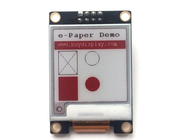
Step 3: Running the Demo
In the Arduino IDE, click File… Examples… ER-EPM0154-1R.
Connect your Arduino to your computer with a USB cable, or however you normally do.
Under Tools, set the Board, Processor and Port.
Under Sketch, click Upload.
There will be a slight delay after uploading completes, and ten the delay will flash a number of times as it paints the first image. Watch while it goes through the demo.
Step 4: Using the Enhanced Library
You can download my enhanced library from github at https://github.com/p-leriche/E-ink_ER-EPM
N.B. I have a high degree of confidence that my library will work with any size compatible display, but I’ve only in fact tested it with the 1.54″ model. If you use a different one, please let me know in the comments at th end of this Instructable, to confirm that it works. But if it doesn’t, I’ll do my best to get you going.
Download and save the zip file. In the Arduino IDE, click Sketch… Include Library… Add .ZIP Library and select the saved zip file.
My library contains several minor enhancements:
- It allows different Arduino pin numbers to be used (except for MOSI).
- The same library can be used forany size device.
- A new 50% shaded fill, and a speckled fill (random pixels set) are provided.
The library comes as a standard Arduino compressed (zip) file. Download it to your Downloads folder (or where you prefer), and in the Arduino IDE, click Sketch… Include Library … Add ZIP Library.
Under Examples, you will now find E-ink_ER-EPM. There are 3 example sketches:
- ER_EPM154-1R-Test: The original vendor-provided demonstration
- E-ink_demo: The sketch developped in the next steps
- E-ink_rotate: A demonstration of image rotation.
Step 5: Programming It Yourself
There is unfortunately no documentation with the vendor-provided code, nor is the example code commented adequately. This makes it harder than it should be to use, and the main purpose of this Instructable is to put that right.
Basic Concepts
Since an Arduino is limited in the amount of RAM available, the library allows you to draw or write in small sections of the screen at a time, upoading them individually to the device’s intermal memory. Only once you have uploaded all the portions you need do you tell it to display what it has in memory.
These sections of screen are known as “Paint” objects. You only need one, and for each section of screen you define its height, width and rotation. When complete, you upload it, defining the position on the screen to load it to and whether it should be black and white or red and white.
The top left hand corner of the screen has horizontal (x) and vertical (y) coordinates (0,0), the bottom left is (0, 151) and the top right is (151, 0).
Initialisation
Open te E-ink_demo sketch in the Arduino IDE and follow it as I describe how to use the library.
At the top of the sketch you will see the following lines, which are always needed:
#include <SPI.h
#include "ER-ERM0154-1.h"
#include "imagedata.h"
#include "epdpaint.h"

#define COLORED     0
#define UNCOLORED   1
    Epd epd;
The #include lines pull in the required libraries. SPI.h is a standard Arduino library but the others form part of the e-ink library.
We define names for UNCOLORED (white) pixels and COLORED (black or red ones). (Note to my fellow Europeans: the American spelling of COLOR is used.)
The Epd epd; line creates the electronic paper device object, on which we will be displaying. This has to be here at the start of the sketch to make it available to bith the setup() and loop() functions.
If you have a different size display you can replace the EPD line by:
Epd epd(WIDTH, HEIGHT);
(having previously defined WIDTH and HEIGHT in #define statements.)
In the same way you can specify non-default pin numbers with:
Epd epd(WIDTH, HEIGHT, BUSY_PIN, RESET_PIN, DC_PIN, CS_PIN);
Within setup() we need to initialise the device as follows:
Serial.begin(9600)
    if (epd.Init() != 0) {
        Serial.print("e-Paper init failed");
        return;
    }
(In fact, epd.Init() never returns an error, but a future enhancement might detect the absence of a display, or a non-functioning one.
Step 6: Writing Text)
In the E-ink_demo, turn your attention to loop(). First, let’s clear the display:
epd.ClearFrame()
(This is not actually necessary if you’re about to display your own image.)
Before we can draw anything (whether text or graphics) we need to create a Paint object to draw on:
  unsigned char image[1024]
  Paint paint(image, 152, 18);    //width should be the multiple of 8
This reserves some space (1024 bytes) and allocates it to the Paint object, ceated by the second line. This is provisionally configured as 152 pixels wide and 18 pixels deep. We can reconfigure it later for reuse as necessary, but note: the width must be a muultiple of 8 since 8 pixels are stored per byte and we can’t split bytes. (It will in fact round it up if necessary, but it can then be puzzling when your display doesn’t look how it should.
Now we must clear the paint object to UNCOLORED (white), then at position (x, y) = (22, 2) we write “e-ink Demo” using a 16-pixel high font, and COLORED (to show against the UNCOLORED background.
  paint.Clear(UNCOLORED)
  paint.DrawStringAt(12, 2, "e-paper Demo", &Font16, COLORED);
Note that the co-ordinates (22, 2) are the top left hand corner of the first character of the string, and are 22 pixels in and 2 pixels down relative to the top left hand corner of the paint object, not the entire display. Text looks best at least one pixel down from the top of the paint object.
The following fonts are available:
Font8 – 5×8 pixels
Font12 – 7×12 pixels
Font16 – 11×16 pixels
Font20 – 14×20 pixels
Font24 – 17×24 pixels
We now just have to send the paint object (“paint”) to the device (“epd”):
epd.SetPartialWindowBlack(paint.GetImage(), 0, 3, paint.GetWidth(), paint.GetHeight());
SetPartialWindowBlack is a method which we apply to the epd object, using the image and its width and depth properties of the paint object. We’re telling it to write this image to the device at (x, y) = (0, 3). And we’re saying the COLORED pixels are to be black.
That wasn’t too hard, was it? Let’s try another one.
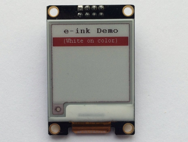
  paint.Clear(COLORED);
  paint.DrawStringAt(20, 2, "(White on color)", &Font12, UNCOLORED);
  epd.SetPartialWindowRed(paint.GetImage(), 0, 24, paint.GetWidth(), paint.GetHeight());
We reuse the same paint object, and the same width and height, but this time, let’s clear it to COLORED and write an UNCOLORED string to it. And for a change, we’ll make the COLORED pixels red and write it to the device at (0, 24), just below the first one.
We’ve written the two paint objects to the device’s memory but not yet told it to display them. We do this with the following statement:
epd.DisplayFrame();
(In the E-ink_demo sketch we actually leave this until the end, after drawing some more stuff, but you could insert it here if you like, mybe followed by delay(10000); to give you time to admire your handiwork.
Source: How to Add an E-Ink Display to Your Project
- Why is an E-Ink display ideal for this project?
It retains the image when switched off, allowing the Arduino to sleep for hours and be powered by a 9V battery for up to 10 years. - What sizes of E-Ink displays are available?
Available sizes include 1.54, 2.13, 2.6, 2.7, 2.9, 4.2, 5.83, and 7.5 inches. - How should the E-Ink module pins be connected to the Arduino?
Pin 1 connects to Vcc, Pin 2 to Gnd, Pin 3 to MOSI, Pin 4 to SCK, Pin 5 to Chip Select, Pin 6 to Data/Instr, Pin 7 to Reset, and Pin 8 to Device Busy. - Where can I download the provided software library?
The library is available as a ZIP file from BuyDisplay.com or via the author's GitHub repository. - What are the benefits of using the enhanced library over the vendor one?
The enhanced library allows custom pin numbers, works with any compatible size, and offers new fill options like 50% shaded and speckled fills. - How do I initialize the e-Paper device in the code?
You must create an Epd object and call epd.Init() within the setup function to initialize the device. - What is the minimum width requirement for a Paint object?
The width must be a multiple of 8 because 8 pixels are stored per byte. - Which fonts are available for drawing text on the display?
Available fonts are Font8, Font12, Font16, Font20, and Font24. - When should you call the DisplayFrame function?
You should call epd.DisplayFrame after writing all paint objects to the device memory to actually show the content. - Can I use yellow instead of red on the display?
Yes, if you have the yellow version, simply read "yellow" wherever the text says "red".