There is no amazing story behind this project – I just always liked the boxing machines, which were located in various popular places. I decided to build mine!
Step 1: Designing
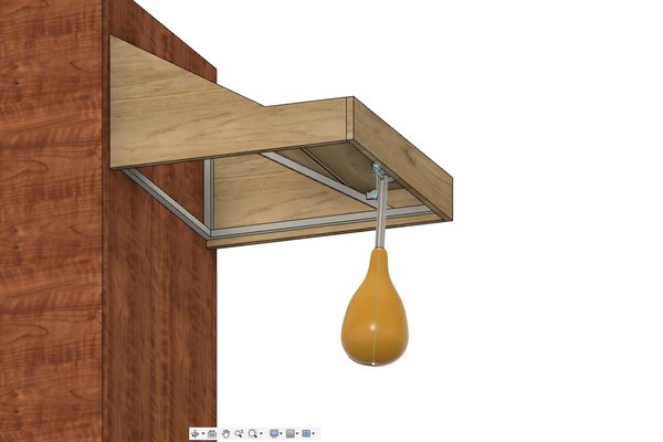
In the beginning, I designed a 3d model of my device. Boxing pear, frame, case and additional parts. Based on the dimensions of this project, I purchased steel profiles and OSB boards. All dimensions and elements used for this project can be found in the file below.
Step 2: Frame Building – Part 1
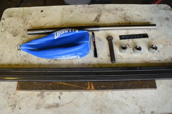
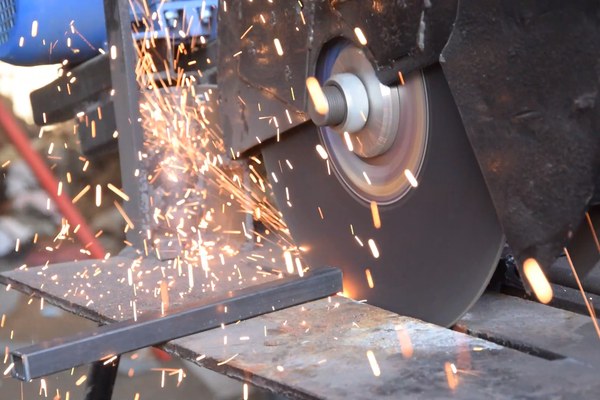
I applied the appropriate dimensions to the steel profiles according to the previously made model and cut all pieces with one of the machines built by my dad. Then, with Dad’s help, I welded the frame structure. I also welded the boxing pear tube to the tube that I will put on the shaft on which the pear will rotate, and then the washers for the holders on that shaft. Finally, I sanded the joints.
Step 3: Frame Building – Part 2
I also adapted the boxing pear to my needs by removing the old handle and creating a new one – from a screw and washer, which I welded together. I put a bolt nut in the tube and welded it on as well. Thanks to this, I will be able to take the pear off when I am not using it, so it will not be damaged. I inflated the balloon in a pear, screwed it to the tube and checked that my construction did not collapse on the first impact. It did not crash. The pear does not stick stiffly, but it does not bother you at all.
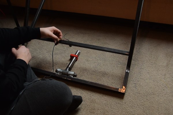
Step 4: Electromagnetic Lock
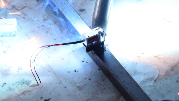
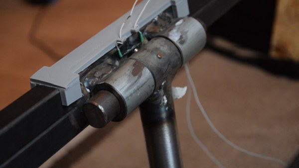
I unscrewed it to weld another steel profile to which I welded the electromagnetic lock, it will be responsible for keeping the boxing pear horizontal. I put a handle for it on the pipe, but it was too weak, so later I tested other methods. Another problem was that the electromagnetic lock did not have the strength to move after applying voltage, the load was too heavy for it.
Step 5: Handles
The first thing that came to my mind was a hook printed on a 3d printer, which will be gently lifted up by a servo. I printed it, subjected it to considerable loads and I must admit that it passed the exam, but I know from experience that after a long time it would deform and would not be usable. However, I designed a servo holder and printed it, and in place of the handle, I welded a piece of steel flat bar. Now I am sure that nothing will come off. I put a piece of rubber on the tube, which I had cut from the old inner tube to reduce noise. I attached another, a thicker piece with ties to reduce the force with which the pipe will hit the steel profile.
Step 6: First Testing
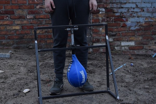
I screwed on the boxing pear and went outside to test the working of the existing project. For this purpose, I hired a professional tester who checked what would happen when the pear hit with cosmic force. What happened? Nothing! So my device works. To be sure, I hired another tester and the result was the same. Great.
Step 7: Electronics
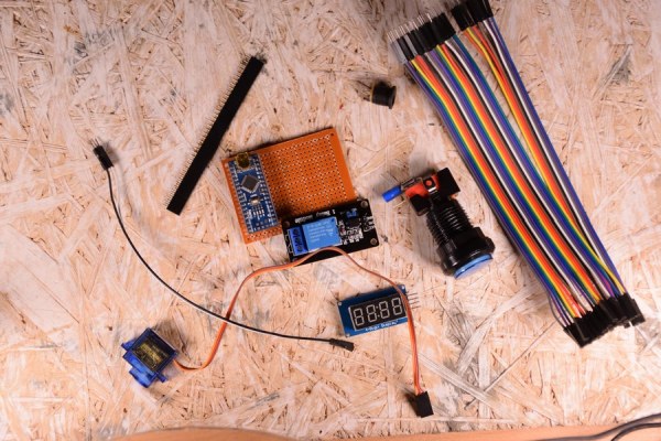
So it’s time for electronics.
I made it exceptionally on a prototype board because this device is just a prototype. This third hand made my soldering easier. I put my PCB on it and soldered the Arduino Nano, resistors and sockets on the PCB. I connected all the elements together according to the diagram. I put the servo in the housing, put it on the steel profile and connected the rest of the elements.
I created this project in cooperation with PCBWay, where I always order PCBs.
Step 8: Debugging
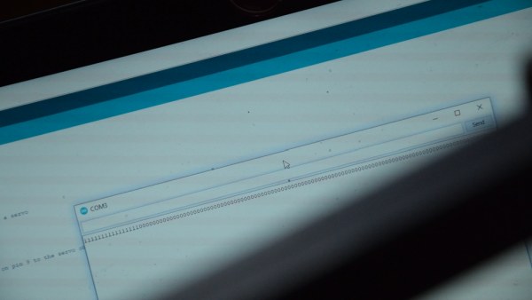
I wrote a simple code for Arduino which, after pressing the button, moves the servo and retracts the electromagnet. The system was doing its job, but with each movement of the electromagnetic lock, the Arduino was resetting. The first problem turned out to be the voltage regulator in the Arduino nano as the 12V was too much for it as it was getting very hot. I decided to use a Step-Down converter, which turned out to be a good solution for a voltage regulator but did not solve the problem of restarting the Arduino. In this situation, a rectifying diode helped, which I connected between the outputs of the electromagnetic lock.
Step 9: Sensor
The next step was the pear position sensor. I made it quite simple – I glued two neodymium magnets on the pear pipe, activating the reed switch on the frame. I wrote another version of the program and went on to create the case.
Step 10: Final Steps
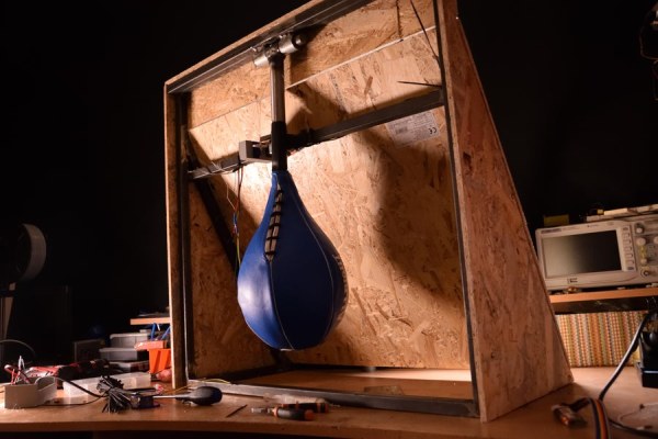
The enclosure is made of OSB boards cut to the appropriate dimensions. I drilled the screw holes in the plates and frame and fastened the plates starting with the side parts and ending with the top. I drilled a larger hole, put a button in it, and connected the display. I updated the earlier code by adding display support and improving the reading of the pear position. The only thing left to do was organize the wires and hang the boxer on the wall.
Step 11: Conclusions

To sum up, I am satisfied with the effects of my device. It is an interesting option for family meetings or competition among friends. Of course, it requires many improvements, such as improving the design or adding sound signals and various game modes. Version 1.1 in a few weeks!
My Youtube: YouTube
My Facebook: Facebook
My Instagram: Instagram
Get 10 PCBs for only $5: PCBWay
Source: How I Made My Own Boxing Machine?