Summary of Homemade CNC Machine From DC Servo Motors and Wooden Wine Boxes
This article details building a 3-axis CNC machine using recycled materials like wooden wine boxes and discarded DC servo motors. The project repurposes old school supplies and electronics, including Arduino boards and stepper drivers, to create a functional plotting device. It covers component selection, assembly of X, Y, and Z axes, control board soldering, and the specific programming logic required to run PID controllers for the servo motors via GRBL firmware.
Parts used in the Homemade 3 Axis CNC Machine:
- Big Wooden Wine Box (350 x 400 x 80 x 8mm)
- Small Wooden Wine Box (220 x 340 x 100 x 10mm)
- Arduino Uno R3
- Arduino Mega 2560
- Arduino CNC Shield V3 GRBL
- Stepper Motor Driver A4988
- Arduino L293D Motor Shield
- DC Servo Motor NISCA NF5475E (2pcs)
- Old CD/DVD Rom Player Drive
- Stepper Motor Support 50 mm (2pcs)
- GT2 6mm Closed Timing Belt 200mm (2pcs)
- GT2 Timing Pulley 60 Teeth (2pcs)
- Round Bar Shaft Rod Diameter 8mm, Length 400mm (4pcs)
- T8 Lead Screw 2mm Pitch, 8mm Lead, Length 400mm with Copper Nut
- Aluminum Flexible Shaft Coupling 10mm x 10mm
- Horizontal Ball Bearing Bracket (12pcs)
- Vertical Ball Bearing Bracket (4pcs)
- F608ZZ Ball Flanged Shielded Bearings 8 x 22 x 7mm (2pcs)
- Single/ Double Sided Printed Prototyping Board
- 2.54mm Pitch 40 Long Pin Single Stackable Shield Female Header (2pcs)
- Male & Female 40 Pin 2.54mm Header (2pcs)
- Power Supply 12VDC – 10A
- Power Supply 5VDC – 5A
- 5mm DC Jack Male Connector (3pcs)
- 5mm DC Jack Female Connector
- 8P Rainbow Ribbon Cable 2 meter
- Clear/White Acrylic A4 Size 5mm thickness (2pcs)
- Black and White Board 2 in 1, A4 Size
- Copper Brass Pillars L-10mm (8pcs)
- Small Size Neodymium Magnets (16pcs)
- Threaded Rod Hangers and Nuts M10 x 500mm (2pcs)
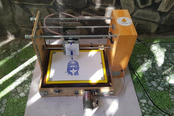
Today, I would like to share how to build a 3 axis CNC machine at home using available or discarded materials. Specifically in this project, I reused 2 old DC servo motors and 2 wooden wine boxes, as well as, taking advantage of my daughter’s unused school supplies.
Step 1: Supplies
The main materials are used in this project:
- 1pcs x Big Wooden Wine Box, dimension W x L x H x T: 350 x 400 x 80 x 8mm.
- 1pcs x Small Wooden Wine Box, dimension W x L x H x T: 220 x 340 x 100 x 10mm.
- 1pcs x Arduino Uno R3.
- 1pcs x Arduino Mega 2560.
- 1pcs x Arduino CNC Shield V3 GRBL.
- 1pcs x Stepper Motor Driver A4988.
- 1pcs x Arduino L293D Motor Shield.
- 2pcs x DC Servo Motor NISCA NF5475E.
- 1pcs x Old CD/DVD Rom Player Drive.
- 2pcs x 50 mm L Stepper Motor Support.
- 2pcs x GT2 6mm Closed Timing Belt 200mm.
- 2pcs x GT2 Timing Pulley 60 Teeth.
- 4pcs x Round Bar Shaft Rod Diameter 8mm, Length 400mm.
- 2pcs x T8 Lead Screw 2mm Pitch, 8mm Lead , Length 400mm with Copper Nut.
- 1pcs x Aluminum Flexible Shaft Coupling, Inner Hole Size: 10mm x 10mm. It is used to clamp the pen/ pencil.
- 12pcs x Horizontal Ball Bearing Bracket.
- 4pcs x Vertical Ball Bearing Bracket.
- 2pcs x F608ZZ Ball Flanged Shielded Bearings 8 x 22 x 7mm.
- 1pcs x Single/ Double Sided Printed Prototyping Board.
- 2pcs x 2.54mm Pitch 40 Long Pin Single Stackable Shield Female Header.
- 2pcs x Male & Female 40 Pin 2.54mm Header.
- 1pcs x Power Supply 12VDC – 10A.
- 1pcs x Power Supply 5VDC – 5A.
- 3pcs x 5mm DC Jack Male Connector.
- 1pcs x 5mm DC Jack Female Connector.
- 2 meter x 8P Rainbow Ribbon Cable.
- 2pcs x Clear/White Acrylic, size A4, thickness 5mm.
- 1pcs x Black and White Board 2 in 1, A4 Size for Kids. It is used for Y axis plotting surface in my case.
- 8pcs x Copper Brass Pillars L-10mm.
- 16pcs x Small Size Neodymium Magnets.
- 2pcs x Threaded Rod Hangers and Nuts M10 x 500mm. I used threaded bolt to reinforce my CNC frame.
- Some small cable ties, cable spiral wrap, M3/M4 bolts and nuts, some kind of steel supports.
Tools:
- Drilling machine with drill bit hole 20mm.
- Soldering machine.
Step 2: Project Schematic
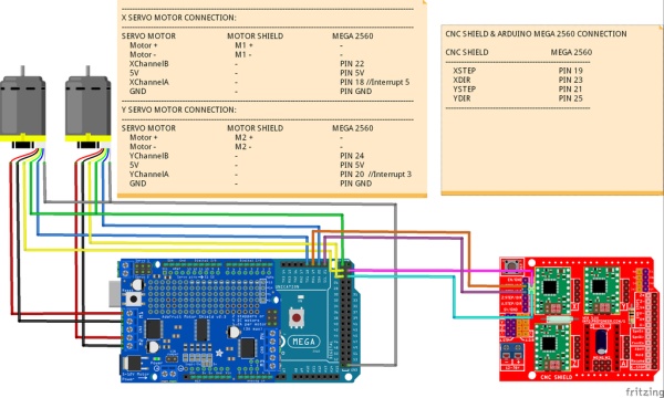
You can download project schematic in PDF format HERE. My CNC is built from 2 DC servo motors for X, Y axis and 1 stepper motor for Z axis.
There are 3 groups in the schematic, I’d like to clarify as follow:
- Group 1 – Red: including Arduino Uno with GRBL firmware pre-installed and CNC Shield. Arduino Uno is responsible for sending control signals: STEP/ DIRECTION to DC servo motor driver X, Y and stepper motor driver Z.
- Group 2 – Blue: including Arduino Mega 2560 and L293D Motor Shield which work like a DC servo motor driver. It received commands STEP/ DIR from Arduino Uno and performs P.I.D control for the X and Y axis. The P.I.D setpoint of DC servo motors in this case are STEP plus DIRECTION signals from GRBL firmware.
- Group 3 – Brown: including DC servo motor X, Y. (The stepper motor Z didn’t shown on my schematic).
Step 3: NISCA DC Servo Motor
Main DC servo motor NF5475E parameters are marked in red rectangular below:
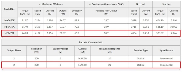
Notes:
- Motor voltage: 24 VDC, 38 VDC (E-type). In my case, I used 12VDC power supply to the motor because this voltage level is compatible with L293D Motor Shield. If you want to use a 24VDC power supply, the motor control module must have a higher voltage level, such as L298N.
- The Encoder needs to be powered by 5VDC and it has two channels A, B. Encoder resolution 200 P/R (200 pulses per revolution) means: Encoder will generate 200 pulses when motor complete one revolution.
For NISCA DC servo motor, we can check detail at : https://ftn.canon/en/product/motor/encoder.html
Step 4: CNC Machine Assembly
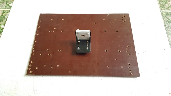
1. Build Y axis
Firstly, I measured the size of the motor, timing belt & pulleys to get the most suitable layout on a big wooden wine box. As you can see, the old dc servo motor has a 20-teeth pulley pre-installed and I used an additional 60-teeth pulley and 200mm closed timing belt to drive the leadscrew.
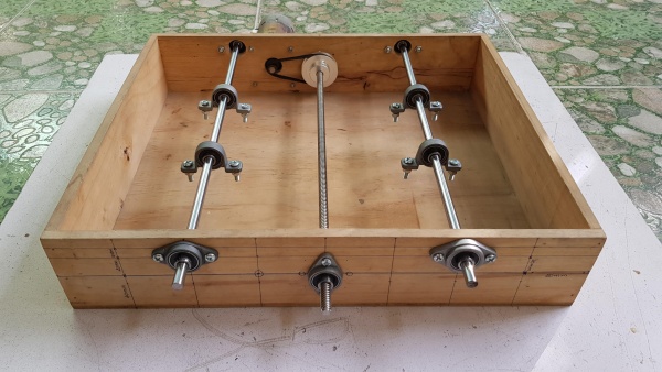
I used 5 pcs x horizontal ball bearing brackets and 1 pcs x ball flanged shielded bearing for the lead screw and shaft rods. The working surface of CNC machine will be mounted to 4 pcs x vertical ball bearing brackets. I used horizontal and vertical ball bearing brackets because I can do some alignments later in case my drilling work could be incorrect.
2. Mounting working surface on Y axis
I used the cover of big wine box for something else, so I used another wooden plate for the working surface.
To clamp copper nut of lead screw, I used a L stepper motor support and 2 acrylic plate, like picture below. The hole diameter as well as thickness of the L support and copper nut are fit together and strong enough by this way.
Connecting working platform to 4 pcs x vertical ball bearing brackets and lead screw.
Aligning the lead screw and shafts to be sure that the working platform worked smoothly by hand.
3. Build X axis
I used a remaining small box to build the X axis structure. As same as Y axis, I used an additional 60-teeth pulley and 200mm closed timing belt to drive the leadscrew.
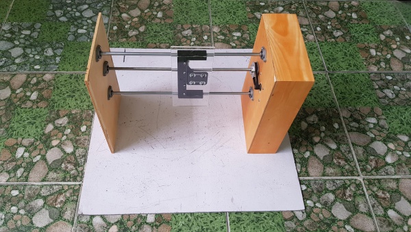
The X axis servo motor was hidden inside the box. One acrylic sheet dimension 100 x 230 mm was installed on the X axis and later one CD drive will be mounted on it for Z axis.
The copper nut of lead screw was clamped by L shape motor support and 2 small acrylic sheets as same as Y axis.
The X and Y axis of CNC machine were finished, then I put them together to align and mark drilling holes.
4. Build the Z axis and reinforcement the CNC frame.
I used one CD player for Z axis and the pen/ pencil is clamped by one aluminum flexible shaft coupling 10 x 10mm.
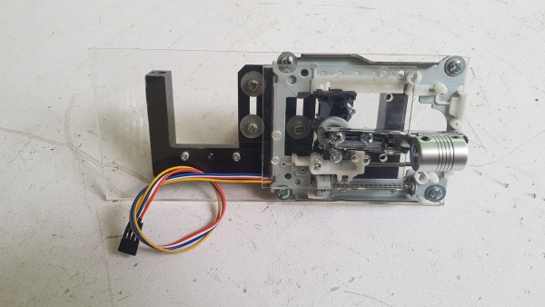
I connected all CNC axis frames together, prepared all wirings and reinforced the CNC structure by some steel supports.
For the plotting platform, I used a black (top) and white (bottom) board, A4 size for kids. I removed yellow plastic border out of the board then I glued this plastic border on the Y axis.
Finally, I did alignment and clamped the black and white board into the plastic border. By this way, I can remove the board from its plastic border if I need to align or tighten the Y-axis bolts.
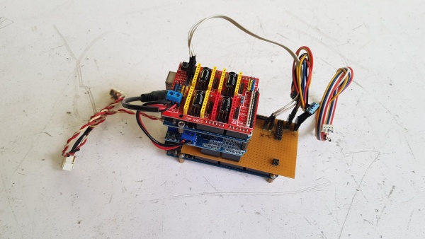
Step 5: Control Board Soldering Works
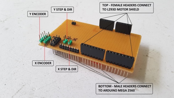
1. Arduino Mega Adapter Shield.
Following the schematic on STEP 2, I cut one PCB prototype board size 60 x 90mm and soldered all the wires connections. Adapter Shield is used for connecting the Arduino Mega 2560 to the L293D Motor Shield, DC servo motor encoders and control signals from GRBL firmware (STEP & DIRECTION) as follow:
- Top female headers: connecting to L293D Motor Shield.
- Bottom male header: connecting to Arduino Mega 2560.
- 4 pins – top male headers: connecting to X Encoders servo motor (5V, GND, Channel A, Channel B).
- 4 pins – top male headers: connecting to Y Encoders servo motor (5V, GND, Channel A, Channel B).
- 2 pins – top male header: connecting to X.STEP and X.DIR signals.
- 2 pins – top male header: connecting to Y.STEP and Y.DIR signals.
Take note the pinout of encoder header on servo motor NF5475E as follow:
If you have a PCB project, you can visit the NEXTPCB website to get exciting discounts and coupons.
- Only $0 for 1-4 layer PCB Prototype: https://www.nextpcb.com/pcb-quote?act=2&code=tune…
- New customer get $100 coupons, register at: https://www.nextpcb.com/register?code=tunendd
2. Control Board Assembly.
I stacked all the boards in following order from bottom:
- Arduino Mega 2560.
- Adapter Shield.
- L293D Motor Shield.
- Arduino Uno.
- CNC Shield.
3. Mouting control boad into box.
I installed control board and power supplies (5VDC – 12VDC) inside the small box and plugged all connections together.
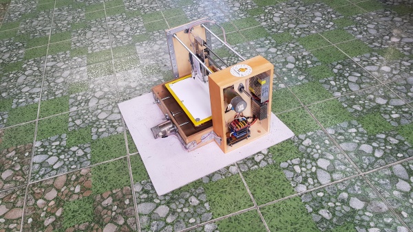
And one power switch was mounted at CNC backside.
Preparing A4 paper for plotting. Done!
Step 6: Programing
The Arduino Mega 2560 code is as below:
/*
   In this project, DC servo motors can be simulated as same as stepper motors and they can be controlled via GRBL firmware for CNC application.
*/

// Timer2 library
#include "FlexiTimer2.h"

// PID library
#include <PID_v1.h>

// AFMotor library
#include <AFMotor.h>

// Quadrature Encoder Library
#include "Encoder.h"

// Create the motor driver instances
AF_DCMotor motorX(1, MOTOR12_8KHZ);
AF_DCMotor motorY(2, MOTOR12_8KHZ);

// Set up pins for the quadrature encoders - Arduino MEGA2560 has 6 interrupt pins.
#define EncoderX_ChannelA   18  // Interrupt 5
#define EncoderX_ChannelB   22
#define EncoderY_ChannelA   20  // Interrupt 3
#define EncoderY_ChannelB   24

// Set up STEP & DIRECTION pins for X and Y axis
#define STEP_XPIN           19  // Interrupt 4
#define STEP_YPIN           21  // Interrupt 2
#define DIR_XPIN            23
#define DIR_YPIN            25

// Turn on/ off debugging for X/Y servo motor
#define DEBUG_X             0   // For X servo motor
#define DEBUG_Y             0   // For Y servo motor

// For calculating the actual movements
#define STEPSPERMM_X      300.0    // STEP/mm is used in the GRBL firmware for DC servo motor X axis.
#define DEADBW_X          30.0     // Deadband width = 30.0 --> Acceptable error for positioning in mm: 0.10mm.

#define STEPSPERMM_Y      300.0   // STEP/mm is used in the GRBL for DC servo motor Y axis.
#define DEADBW_Y          30.0    // Deadband width = 30.0 --> Acceptable error for positioning in mm: 0.10mm.


// Set up Input
double INPUT_X;
double INPUT_Y;

double OLD_INPUT_X = 0;
double OLD_INPUT_Y = 0;

// Set up Actual value
double ACTUAL_X_MM;
double ACTUAL_Y_MM;

double OLD_ACTUAL_X_MM;
double OLD_ACTUAL_Y_MM;

// PID controller constants
double KP_X = 10.0;     // P for X servo motor
double KI_X = 0.03;     // I for X servo motor
double KD_X = 0.01;     // D for X servo motor

double KP_Y = 10.0;     // P for Y servo motor
double KI_Y = 0.03;     // I for Y servo motor
double KD_Y = 0.01;     // D for Y servo motor

// The Output variable motor speed to the motor driver
double OUTPUT_X;
double OUTPUT_Y;
double OLD_OUTPUT_X = 0;
double OLD_OUTPUT_Y = 0;

// Setpoint
double SETPOINT_X = 0;
double SETPOINT_Y = 0;

double OLD_SETPOINT_X = 0;
double OLD_SETPOINT_Y = 0;

double ERROR_X = 0;
double ERROR_Y = 0;

// Direction
int directionX;
int directionY;

// PID controller
PID myPID_X(&INPUT_X, &OUTPUT_X, &SETPOINT_X, KP_X, KI_X, KD_X, DIRECT);
PID myPID_Y(&INPUT_Y, &OUTPUT_Y, &SETPOINT_Y, KP_Y, KI_Y, KD_Y, DIRECT);

// Setup optical encoders
Encoder XEncoder(EncoderX_ChannelA, EncoderX_ChannelB);
Encoder YEncoder(EncoderY_ChannelA, EncoderY_ChannelB);

void setup()
{
  // For debugging
  if (DEBUG_X || DEBUG_Y)
  {
  Serial.begin(115200);
  }

  pinMode(STEP_XPIN, INPUT);
  pinMode(STEP_YPIN, INPUT);
  pinMode(DIR_XPIN, INPUT);
  pinMode(DIR_YPIN, INPUT);

  // The stepper simulator
  attachInterrupt(4, doXstep, RISING);  // PIN 19 (Interrupt 4) - Interrupt X step at rising edge pulses
  attachInterrupt(2, doYstep, RISING);  // PIN 21 (Interrupt 2) - Interrupt Y step at rising edge pulses

  // Outpout PWM limits
  myPID_X.SetOutputLimits(-255, 255);
  myPID_Y.SetOutputLimits(-255, 255);

  // Compute output every 1ms
  myPID_X.SetSampleTime(1);
  myPID_Y.SetSampleTime(1);

  // Setup PID mode
  myPID_X.SetMode(AUTOMATIC);
  myPID_Y.SetMode(AUTOMATIC);

  // Apply PID every 1ms by FlexiTimer2
  FlexiTimer2::set(1, 1.0 / 1000, doPID);
  FlexiTimer2::start();
}

void loop()
{
  // Read X and Y axis servo encoders
  INPUT_X = XEncoder.read();
  INPUT_Y = YEncoder.read();

  // Calculating the error
  ERROR_X = (INPUT_X - SETPOINT_X);
  ERROR_Y = (INPUT_Y - SETPOINT_Y);

  // For debugging
  if (DEBUG_X)
  {
    ACTUAL_X_MM = INPUT_X / STEPSPERMM_X;
    // Debugging X motor actual position in mm
    if (OLD_ACTUAL_X_MM != ACTUAL_X_MM)
    {
      Serial.print("ACTUAL X(MM): ");
      Serial.println(ACTUAL_X_MM);
      OLD_ACTUAL_X_MM = ACTUAL_X_MM;
    }
    // Debugging position X encoders
    if (OLD_INPUT_X != INPUT_X)
    {
      Serial.print("POSITION X: ");
      Serial.println(INPUT_X);
      OLD_INPUT_X = INPUT_X;
    }
    // Debugging X stepping input
    if ( SETPOINT_X != OLD_SETPOINT_X )
    {
      Serial.print("SETPOINT X: ");
      Serial.println(SETPOINT_X);
      OLD_SETPOINT_X = SETPOINT_X;
    }
    // Debugging X motor PWM output
    if ( OUTPUT_X != OLD_OUTPUT_X )
    {
      Serial.print("OUTPUT X: ");
      Serial.println(OUTPUT_X);
      OLD_OUTPUT_X = OUTPUT_X;
    }

  }
  if (DEBUG_Y)
  {
    ACTUAL_Y_MM = INPUT_Y / STEPSPERMM_Y;
    // Debugging Y motor actual position in mm
    if (OLD_ACTUAL_Y_MM != ACTUAL_Y_MM)
    {
      Serial.print("ACTUAL Y(MM): ");
      Serial.println(ACTUAL_Y_MM);
      OLD_ACTUAL_Y_MM = ACTUAL_Y_MM;
    }
    // Debugging Y stepping input
    if ( SETPOINT_Y != OLD_SETPOINT_Y )
    {
      Serial.print("SETPOINT Y: ");
      Serial.println(SETPOINT_Y);
      OLD_SETPOINT_Y = SETPOINT_Y;
    }
    // Debugging position Y encoders
    if (OLD_INPUT_Y != INPUT_Y)
    {
      Serial.print("POSITION Y: ");
      Serial.println(INPUT_Y);
      OLD_INPUT_Y = INPUT_Y;
    }
    // Debugging Y motor PWM output
    if ( OUTPUT_Y != OLD_OUTPUT_Y )
    {
      Serial.print("OUTPUT Y: ");
      Serial.println(OUTPUT_Y);
      OLD_OUTPUT_Y = OUTPUT_Y;
    }

  }
}

void doXstep()
{
  if ( digitalRead(DIR_XPIN) == HIGH ) SETPOINT_X--;
  else SETPOINT_X++;
}

void doYstep()
{
  if ( digitalRead(DIR_YPIN) == HIGH ) SETPOINT_Y--;
  else SETPOINT_Y++;
}

void doPID()
{
  interrupts();
  myPID_X.Compute();
  myPID_Y.Compute();
  if (abs(ERROR_X) < DEADBW_X) // If servo motor X is in position within the deadband width (acceptable error)
    {
      motorX.setSpeed(0); // Turn off servo motor X
    }
  else
    {
      motorX.setSpeed(abs(int(OUTPUT_X)));  // Servo motor X is regulated by PID controller ouput
    }
  if (abs(ERROR_Y) < DEADBW_Y) // If servo motor Y is in position within the deadband width (acceptable error)
    {
      motorY.setSpeed(0); // Turn off servo motor Y
    }
  else
    {
      motorY.setSpeed(abs(int(OUTPUT_Y)));  // Servo motor Y is regulated by PID controller ouput
    }
  int directionX;
  int directionY;

  if(OUTPUT_X > 0)
    {
      directionX = FORWARD;
    }
  if(OUTPUT_X < 0)
    {
      directionX = BACKWARD;
    }

  if(OUTPUT_Y > 0)
    {
      directionY = FORWARD;
    }
  if(OUTPUT_Y < 0)
    {
      directionY = BACKWARD;
    }

  motorX.run(directionX);
  motorY.run(directionY);
}<br>
Source: Homemade CNC Machine From DC Servo Motors and Wooden Wine Boxes
- What main materials are reused in this CNC project?
The project uses two old wooden wine boxes, two discarded DC servo motors, and unused school supplies like an old CD/DVD drive. - How is the Arduino Uno utilized in the control system?
The Arduino Uno runs GRBL firmware to send STEP and DIRECTION control signals to the motor drivers for the X, Y, and Z axes. - Can I use a 24VDC power supply for the NISCA DC servo motors?
You can use 24VDC if your motor control module supports higher voltage levels, such as the L298N, but the L293D shield requires 12VDC. - What components are used to build the Y axis structure?
The Y axis is built using a big wooden wine box, horizontal ball bearing brackets, vertical ball bearing brackets, and a lead screw with a copper nut. - How does the PID controller function in the Arduino code?
The PID controller compares encoder input with the setpoint to calculate error and adjusts the motor speed output to maintain precise positioning. - What drives the Z axis movement in this design?
The Z axis is driven by an old CD/DVD player drive, which holds the pen or pencil using an aluminum flexible shaft coupling. - How is the working surface mounted on the Y axis?
A wooden plate is clamped to four vertical ball bearing brackets and connected to the lead screw to form the moving working platform. - What libraries are included in the Arduino Mega 2560 program?
The code includes FlexiTimer2, PID_v1, AFMotor, and Quadrature Encoder libraries to manage timing, control loops, and motor driving.