Movies look cool with those EKG (electrocardiogram), the one that beeps and detects heart activities. A few months ago, we had to shoot a hospital scene for our school project. We needed an EKG instrument. To keep the movie authentic, we didn’t want to fake the readings so we made the next best thing, a pulse monitor. Since my dad is a doctor he gave me some advice to design the pulse monitor.
Let me clarify this to you. This project works and can actually monitor your pulse. Due to the lack of research and experimentation, the homebrew pulse monitor cannot be used for medical purposes.
What Can You Do With It?
You can make a lie detector/ polygraph and tell who’s lying or not. When a person lies, you’ll notice a sudden change on the graph.
 What Does This Guide Include?
– Arduino Codes & Processing 2 Codes
– Steps on making a pulse sensor
– The Virtual Graphing Software
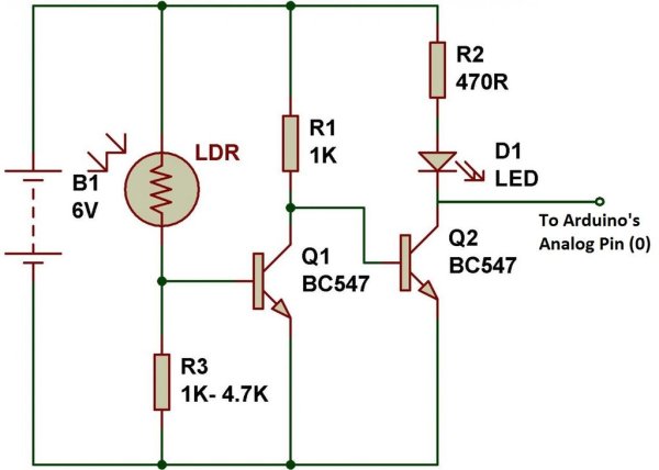
– Schematic Diagrams
What Do I Need To Make This Project?
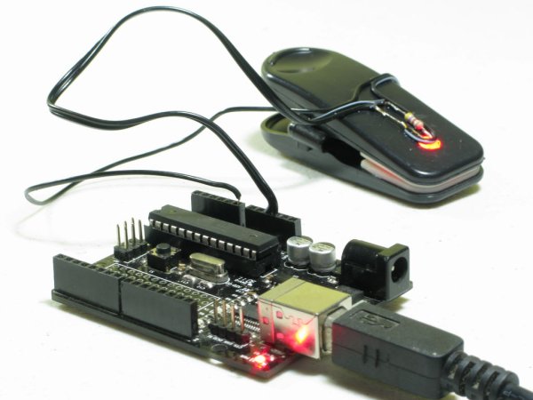
– A Grippy Clothes Hanger
– Clear/ Bright Red LED
– LDR (Light Dependent Resistor)
Future Questions:
Why isn’t mine working? For some reason LDRs (light dependent resistors) are not standard in resistance ratings. You’ll need a some tweaking to pull off the project, it may require experience with Arduinos and electronics.
This project is inspired by Make Magazine’s pulse monitor although my version didn’t use a LM324 Op-Amp chip. Their tutorial will work on my setup.
Step 1: Find The Perfect Colthes Hanger
Step 2: Cut The Clips
Step 3: Disassemble The Clip
Step 4: Drill Holes
Step 5: Install The LDR
Step 6: Install The LED
Step 7: It Doesn’t Work
Step 8: Wire Them Up
Step 9: Download The Softwares
Processing 2 is the graph/ monitor software that will visualize your data while the Arduino IDE is for uploading the arduino sketch. You’ll need both to run the project. Click on the links below to download them.
For more detail: Homebrew Arduino Pulse Monitor (Visualize Your Heartbeat)