Summary of Home Automation using Bluetooth of ESP32 with Videos (Hindi & English)
This project uses the ESP32 development board's Classic Bluetooth to control GPIO (an LED) via a custom Android app. It explains required materials, Arduino IDE setup for ESP32, key code components (library declarations, UUIDs, two callback classes, setup with UART/BLE server, baud 115200, LED on pin 5), circuit wiring for one LED, and using/editing the Android app built with Thunkable. Links to ESP-IDF docs, code, app .apk, and tutorial videos are provided.
Parts used in the Bluetooth ESP32 LED Control Project:
- ESP32 NodeMCU development board
- USB Type C cable (for programming)
- LED
- Resistor (1K)
- Breadboard
- Android device (to run the custom app)
- Arduino IDE (software)
In this project, we will be dealing with the inbuilt Bluetooth feature in ESP32 Development board and try to build an application around it.

The Bluetooth system can be divided into two different categories: Classic Bluetooth and Bluetooth Low Energy (BLE). ESP32 supports dual-mode Bluetooth, meaning that both Classic Bluetooth and BLE are supported by ESP32. Here, we will control General Purpose Input Output (GPIO) pins of the ESP32 board using Bluetooth in classic mode and a customized Android application.
For more documentation, you can refer to Espressif IoT Development Framework here. So, let’s get started.
Material required for the Bluetooth project
1. ESP32 NodeMCU (Check the datasheet, if you are using a different version.)
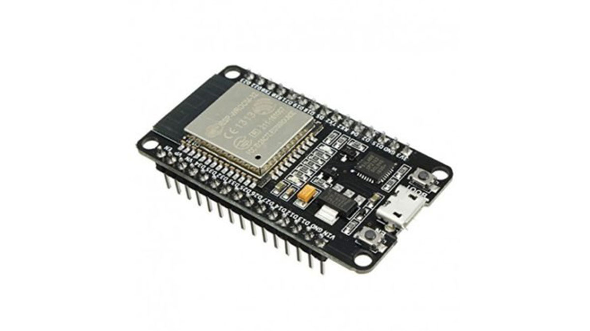
ESP32
2. USB Type C cable to program ESP32 from a laptop or PC (most Android phones use this type of cable).
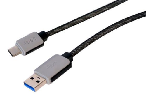
USB Cable
3. LED with Resistor(1K) – To test the Bluetooth
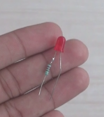
LED with a resistor
4. Breadboard – To place the components
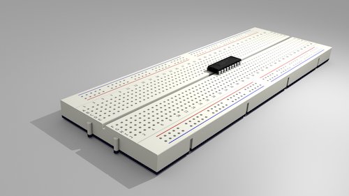
Breadboard
Steps for the ESP32 support in Arduino IDE:
(Ignore this step if you already have the setup of ESP boards in Arduino IDE)
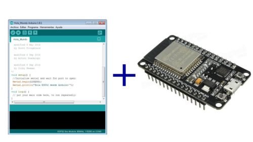
ESP32 support in Arduino IDE
Here, to program the ESP32 we need an Integrated Development Environment and we will use Arduino IDE software. Arduino IDE is a cross-platform application. It is written in Java and coded in C/C++ with some special rules. To download the latest Arduino IDE from here.
Arduino IDE does not contain support of ESP32 family so to install the ESP-32 Board in Arduino IDE, you can refer here.
The Code for Bluetooth in ESP32
Download the Code from the link below and Open it in Arduino IDE. Let’s understand the code.
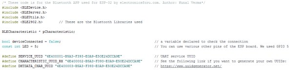
Code declarations
Firstly, we will declare the Bluetooth libraries in the code. All the declaration like Led pin, states and UUIDs are declared here. To have more details on UUID refer here.
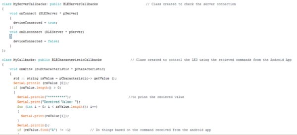
Classes
Then, we will create two classes. MyServerCallbacks is created to check the server connection and MyCallbacks to perform the various functions.
Hence, this function contains the LED controlling part of the Bluetooth and prints the value received. One may also include some inputs to fetch data like temperature or humidity. The android application will give commands like “A” and “B” which will be received by the ESP-32 BLE and will generate the same results. These classes are created to call in the Void Setup() and most of the part of the code is set up here only.
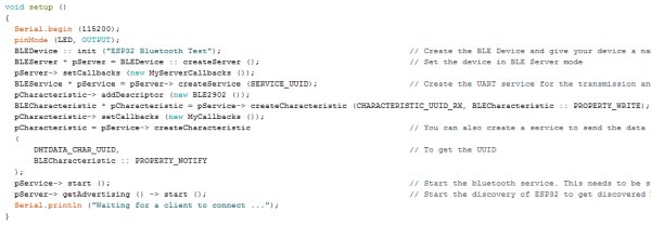
Void Setup()
All the characteristics of Bluetooth and device name will be declared here including the start of various services like UART and BLE Server.
The baud rate is by default set to 115200 and pin 5 declared as LED will be set to OUTPUT.
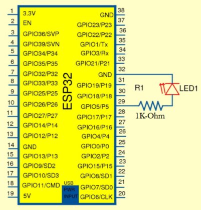
Circuit Connections:
There is only one Output (LED) in the circuit you can add many more outputs or set inputs.
ESP32 Pin 5 -> Resistor
Resistor -> LED +ve
LED -ve -> Ground
Connections
Using the Android Application:
You can download the android application from here(.apk download link) and use it or edit this using Thunkable.

Thunkable
We have created this app for the ESP Bluetooth and you may use it to control the LED or Light.
Read More Detail :Home Automation using Bluetooth of ESP32 with Videos (Hindi & English)
- What Bluetooth modes does ESP32 support?
ESP32 supports dual-mode Bluetooth: Classic Bluetooth and Bluetooth Low Energy (BLE). - Which Bluetooth mode is used in this project to control GPIO?
The project uses Classic Bluetooth mode to control GPIO (an LED) via a customized Android app. - What components are required to test the Bluetooth LED control?
Required components are an ESP32 NodeMCU, USB Type C cable, LED with 1K resistor, and a breadboard. - Which Arduino IDE setup step is needed for ESP32?
You must install ESP32 board support into Arduino IDE if not already set up, following the linked instructions. - Which pin is used for the LED in the example code?
Pin 5 is declared as the LED pin and set as OUTPUT in void setup(). - What baud rate is used by default in the project?
The baud rate is set to 115200 by default. - How is the LED wired to the ESP32?
ESP32 pin 5 connects to the resistor, resistor to LED positive, and LED negative to ground. - What does the Android app send to the ESP32 to control the LED?
The Android app sends simple commands like A and B which the ESP32 receives and acts upon to control the LED. - Can the project be extended to read sensors?
Yes; the article notes one may include inputs to fetch data like temperature or humidity in addition to LED control.