Summary of Home Automation Using Arduino With Wifi, Bluetooth and IR Remote Control
This tutorial details building a scalable home automation system using three Arduino Uno boards. The master-slave setup connects via I2C, enabling control through Wi-Fi (ESP8266-01), Bluetooth voice commands (HC-05), and IR remotes. It features sensor integration for temperature, humidity, and motion, alongside an LCD display and real-time clock, all powered by a custom 5V AC-to-DC supply circuit.
Parts used in the Home Automation System:
- 3x Arduino Uno or Atmega328 / Atmega328p
- ESP8266-01
- HC-05 Bluetooth module
- TSOP IR receiver
- IR remote
- Nokia 5110 display
- RTC (DS1307) real time clock
- 12-0-12 1A step down transformer
- Bridge rectifier / 4x diodes (1N4001)
- 1000uF, 25v capacitor
- DC-DC stepdown buck convertor
- LM1117 or LM317 voltage regulator
- PIR (passive infrared) sensor
- DHT11 (Temperature and humidity) sensor
- Breadboard, strippers, wires, jumpers, glue, sticky tapes
This is a tutorial to show how to build a home automation system using arduino with Wifi [ESP8266-01], bluetooth (HC-05) and IR remote control. Home automation results in a smarter home and is used to provide a higher and healthier standard of living. The beauty of a home automation system is that it is highly scalable, flexible and its capabilities are limited only by our imagination.
Step 1: Overview of the Home Automation System
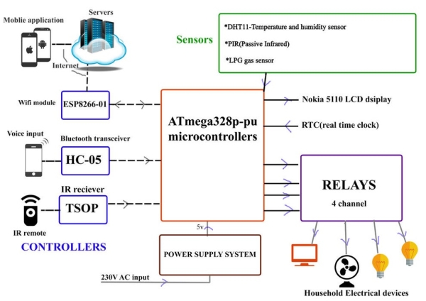
This systems consists of 3 custom built arduino uno boards, two of which are connected to each other via I2C bus, one of which acts as a “master sender” and the other a “slave reciever”. Home automation system can be controlled using Internet, which is achieved by using ESP8266-01 and blynk libraries. It also allows us to control the system by giving voice commands using HC-05 bluetooth module and AMR voice app.
I have explained interfacing each of the components to the microcontroller.
Materials needed:
* 3x arduino uno or Atmega328 / Atmega328p
*ESP8266-01,
*HC-05
*TSOP IR receiver
*IR remote.
*nokia 5110 display
* RTC (DS1307) real time clock
To build your own 5V Power supply from 230v / 110v ac-
*12-0-12 1A step down transformer
*Bridge rectifier / 4x diodes(1N4001)
*1000uF, 25v capacitor
*DC-DC stepdown buck convertor
*LM1117 or LM317 to get 3.3V power supply for ESP8266-01
SENSORS
*PIR (passive infrared)
*DHT11(Temperature and humidity)
* other materials such as breadboard, strippers, wires, jumpers, glue, sticky tapes etc..
Step 2: Circuit Diagram
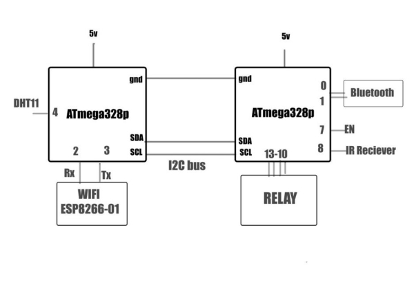
The main control center of system are the three ATmega328p microcontroller. This part of the system manages the controllers and gets the commands from the user. It also sends temperature and humidity measurement to the mobile application. ATmega328p also gets sensor data and processes them to perform useful functions. The microcontroller also switches the relays to turn on/off the electrical devices when required. It displays the date and time using the RTC and the LCD display device.
Step 3: POWER SUPPLY
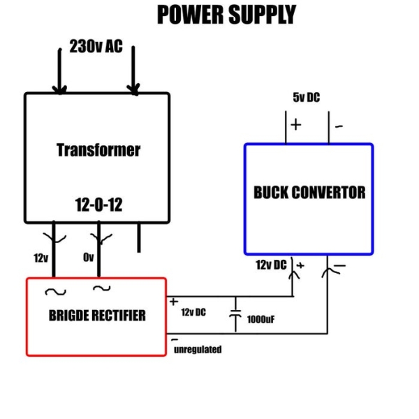
The micro controllers need 5V DC power supply, this is obtained from 230V AC supply.
* A 12-0-12, 1A STEP DOWN transformer converts 230v AC to 12V AC.
*12V AC is converted to unregulated DC by passing it through a BRIDGE RECTIFIER and A 1000uF capacitor.
*12V DC (unregulated) is applied at the inputs of a DC-DC step down BUCK CONVERTER.The buck converter is adjusted to get output voltage of 5V DC.
* Buck converters are highly efficient over linear regulators(LM7805).
Read more: Home Automation Using Arduino With Wifi, Bluetooth and IR Remote Control
-
How is the home automation system controlled?
The system can be controlled via the Internet using ESP8266-01 and Blynk libraries, through voice commands using the HC-05 Bluetooth module with the AMR voice app, and via an IR remote. -
What components make up the main control center?
The main control center consists of three ATmega328p microcontrollers connected via an I2C bus, where one acts as a master sender and another as a slave receiver. -
How is the 5V DC power supply generated from AC mains?
A 12-0-12 transformer converts 230V AC to 12V AC, which is then rectified by a bridge rectifier and smoothed by a capacitor before being stepped down to 5V DC by a buck converter. -
Which sensors are used in this project?
The project uses a PIR passive infrared sensor for motion detection and a DHT11 sensor for measuring temperature and humidity. -
Why is a buck converter preferred over linear regulators like LM7805?
Buck converters are considered highly efficient compared to linear regulators such as the LM7805. -
What is the purpose of the LM1117 or LM317 in this circuit?
The LM1117 or LM317 is used to generate a 3.3V power supply specifically required for the ESP8266-01 module. -
How does the system handle date and time information?
The microcontroller switches relays and displays the current date and time using an RTC (DS1307) and an LCD display device.