In this project we are going to make a home automation system using ESP8266 WiFi module and Arduino Uno. Using this we will be able to control lights, electric fan and other home appliances through a web browser using your PC or mobile. These AC mains appliances will be connected to relays which are controlled by the Arduino. ESP8266 and Arduino together acts as a Web Server and we will send control commands through a Web Browser like Google Chrome or Mozilla Firefox. ESP8266 is the one of the most popular and low cost wifi module available in the market today. You can ready more about it here, ESP8266 – WiFi SoC.
ESP-01 ESP8266 Module
ESP-01 is the one of the most popular ESP8266 module available in the market. ESP8266 is a self contained SoC with integrated TCP/IP stack which helps any microcontroller having UART to access a wifi network. It can act as both WiFi access point as well as a WiFi client. It is pre-programmed with AT commands, so we can easily access and configure it using a microcontroller.
ESP8266 runs on 3.3V and its input pins are not 5V tolerant. So we need to reduce the 5V output of the Arduino Tx pin to 3.3V by using voltage dividing resistors to connect to Rx pin of ESP8266 module. Arduino TTL input pins will detect 3.3V as logic high, so we can directly connect 3.3V output of ESP8266 Tx to Arduino Rx pin.
Circuit Diagram and Explanation
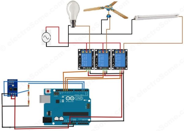
First we can connect ESP8266 with the Arduino Uno. The ESP8266 runs on 3.3V, it may damage if you connect it directly to 5V from Arduino. The pin out of the ESP-01 ESP8266 module is shown below.
Connect the VCC and CH_PD of the ESP8266 to the 3.3V output pin of Arduino. CH_PD is Chip Power Down pin, which is active low. So we will give 3.3V to it, which will enable the chip. Then connect the TXD pin of the ESP8266 with the digital pin 2 of the Arduino. Then make a voltage divider to make 3.3V for the RXD of the ESP8266 which is connected to the pin 3 of Arduino. Here we are using software UART through digital pins 2 & 3 of Arduino. Lastly, connect the ground of the ESP8266 with the ground of the Arduino.
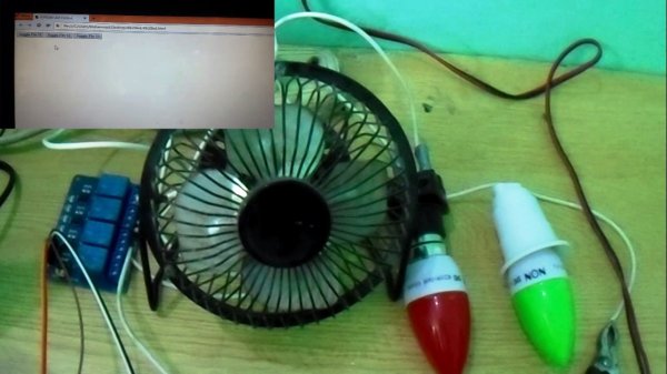
Now we can connect relays to Arduino. Connect three relays to pins 11, 12 and 13 of the Arduino. Also connect 5V and ground from the Arduino to power the relay. Note that here I am using relay modules which having built in transistor driver. So don’t forget to add driver when you are using bare relays. We can connect AC devices to the output terminals of those relays. First connect one wire (Phase) of the AC source with the common terminal (COM) of all relays and the second wire (Neutral) of AC source to one terminal of AC devices. Then connect the other terminal of AC devices to the NO (Normally Open) terminal of relays.
Program
Arduino Sketch
#include <SoftwareSerial.h>  //Including the software serial library
#define DEBUG true
SoftwareSerial esp8266(2,3); // This will make the Arduino pin 2 as the RX pin and Arduino pin 3 as the TX. Software UART
/* So you have to connect the TX of the esp8266 to the pin 2 of the Arduino and the TX of the esp8266 to the pin 3 of the Arduino. This means that you need to connect the TX line from the esp to the Arduino's pin 2 */

void setup()
{
  Serial.begin(9600);   // Setting the baudrate to 9600
  esp8266.begin(9600);  // Set it according to your esp’s baudrate. Different esp’s have different baud rates.
  pinMode(11,OUTPUT);   // Setting the pin 11 as the output pin.
  digitalWrite(11,LOW); // Making it low.
  pinMode(12,OUTPUT);   // Setting the pin 12 as the output pin..
  digitalWrite(12,LOW); // Making pin 12 low.
  pinMode(13,OUTPUT);   // Setting the pin 13 as the output pin.
  digitalWrite(13,LOW); // Making pin 13 low.
  sendData("AT+RST\r\n",2000,DEBUG);            //This command will reset module to default
  sendData("AT+CWMODE=2\r\n",1000,DEBUG);       // This will configure the mode as access point
  sendData("AT+CIFSR\r\n",1000,DEBUG);          // This will get ip address and will show it
  sendData("AT+CIPMUX=1\r\n",1000,DEBUG);       // This will configure the ESP8266 for multiple connections
  sendData("AT+CIPSERVER=1,80\r\n",1000,DEBUG); // This will set the server on port 80
}
void loop()
{
  if(esp8266.available()) // Checking that whether the esp8266 is sending a message or not (Software UART Data)
  {
    if(esp8266.find("+IPD,"))
    {
      delay(1000);        // Waiting for 1 sec
      int connectionId = esp8266.read()-48;   // Subtracting 48 from the character to get the number.
      esp8266.find("pin=");                   // Advancing the cursor to the "pin="
      int pinNumber = (esp8266.read()-48)*10; // Getting the first number which is pin 13
      pinNumber += (esp8266.read()-48);       // This will get the second number. For example, if the pin number is 13 then the 2nd number will be 3 and then add it to the first number
      digitalWrite(pinNumber, !digitalRead(pinNumber)); // This will toggle the pin
      // The following commands will close the connection
      String closeCommand = "AT+CIPCLOSE=";
      closeCommand+=connectionId;
      closeCommand+="\r\n";
      sendData(closeCommand,1000,DEBUG);     // Sending the data to the ESP8266 to close the command
    }
  }
}
String sendData(String command, const int timeout, boolean debug) // Function to send the data to the esp8266
{
  String response = "";
  esp8266.print(command);           // Send the command to the ESP8266
  long int time = millis();
  while( (time+timeout) > millis()) // ESP8266 will wait for some time for the data to receive
  {
    while(esp8266.available())      // Checking whether ESP8266 has received the data or not
    {
      char c = esp8266.read();      // Read the next character.
      response+=c;                  // Storing the response from the ESP8266
    }
  }
  if(debug)
  {
    Serial.print(response);         // Printing the response of the ESP8266 on the serial monitor.
  }
  return response;
}
Read More: Home Automation using Arduino and ESP8266 Module