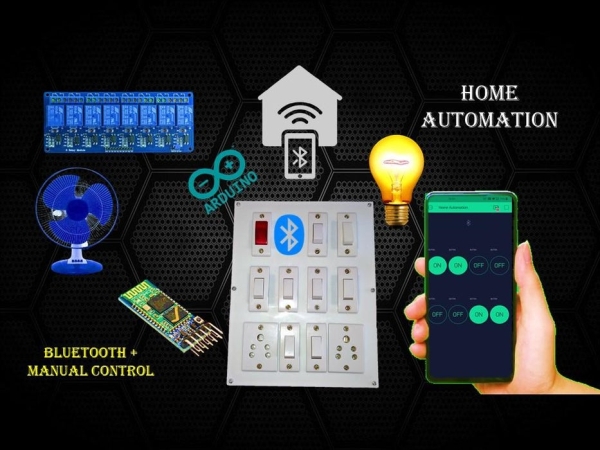
Hello friends welcome back to “Techno-E-solution”, In previous video we see how we can control the home appliances with the help of Smartphone & Bluetooth but there is no any manual control for the system, so In this tutorial we are going to make a Smartphone control as well as manual controlled home automation system with Complete details.
If you like my project visit my youtube channel for my latest project also follow me on
Youtube :- Click Here
Facebook :- Click Here
Instagram :- Click Here
Instructables :- Click Here
Dailymotion :- Click Here
Let’s get started……………
Part one Of this project :-
Step 1: MATERIAL REQUIRED
The following material are used in the project
Electronic Components :-
- Arduino Nano
- Bluetooth Module (hc-05)
- 8-Channel Relay Module
- LM 2596 DC-DC Buck Convertor
- Red LED (5mm)
- Resistor (470E)
- Male – Female Berge Strip
- 2-Pin Block Connector
- Female-Female Berge Connector Wire
- Single Layer Copper Clad PCB Board
- Power Supply (12V, 1amp)
Hardware / Other Material :-
- PVC Switch Board
- Two way Switch x 8
- 5-Pin socket x 2
- PCB Drill Machine
- Mini Hack Saw
- Ferric Chloride
- Container
- Iron
- Photo Paper
- Laser Printer (Tonner Filled)
- Screw Driver
- Soldering Kit
Step 2: CIRCUIT DIAGRAM
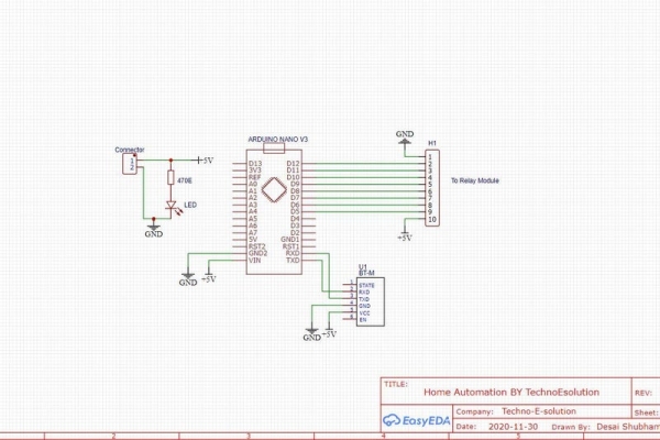
For making Circuit & PCB I used Easy EDA Software, I Provide the PCB layout just print and use tonner transfer method to make PCB.
Step 3: LET’S MAKE PCB
Follow the following process for Making PCB Using Tonner Transfer Technic.
If you want to real PCB, I provide Gerber file below check it.
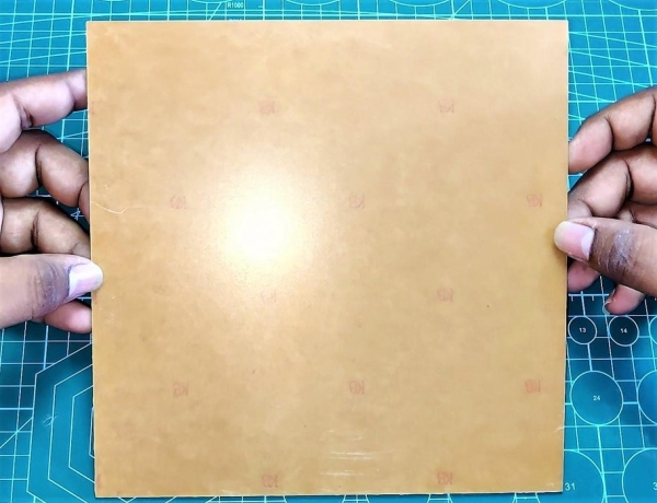
- Take a Single Sided Copper Clad PCB Board
- Cut the PCB as per PCB Layout
- Remove the dirt & rust from the PCB by using wire scrub or sand paper
- Place layout print on PCB & Heat the PCB with the help of Iron for 5-10 Min
- Take water in the container & deep the PCB into the water for 5 min
- Slowly remove the paper from the PCB
- Now take 2-3 spoon of ferrite chloride powder in container with water
- Deep PCB into the solution for 5-10 min for etching process
- After etching completed clean the excessive tonner from the PCB
- Drill The PCB with the help of PCB drill machine
- Now place app components on PCB & Solder It
- In this way the PCB board is completed.
Next PCB
NextPCB is a high-quality PCB Manufacturer. With professional PCB manufacturing capabilities, our PCB engineers with more than 10 years of experience will double-check your engineering files.
NextPCB is certified by IATF16949, ISO9001, ISO14001, UL, CQC, RoHS and REACH; more importantly, we handle the whole process including the PCB prototype, PCB manufacturing, PCB assembly, testing, and final shipment. We are capable of assembling BGA, Micro-BGA, QFN, and other leadless package parts. We also have an online parts shop, you can choose any parts you need.
If you are want to make PCB go through the NEXT PCB
Download PCB Gerber File:- Click To Download
Step 4: BLYNK APP INSTALLATION & SETUP
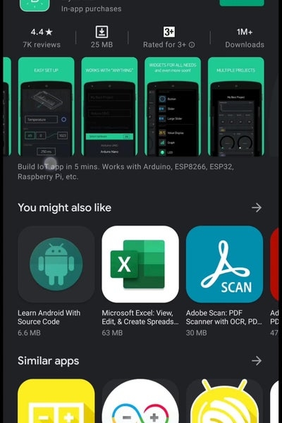
- Install Blynk App from google play store.
- Create Account On Blynk.
- Create New Project.
- You will get Tocken on your E-Mail.
- Give Name to Project.
- Select Device & Connection Type & click on Create Button.
- Select Bluetooth, then add 8 buttons.
- Give name to Buttons.
- Set the Pins.
- The app setup is completed
Step 5: ARDUINO PROGRAMMING
- Add Blynk library in your Arduino IDE
- Sketch-Include Library-Manage libraries-Type Blynk-
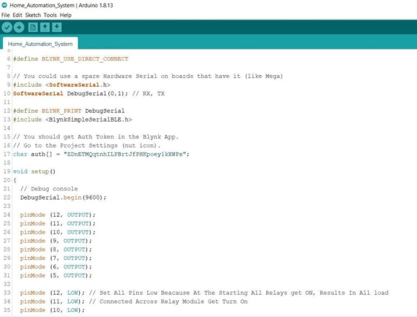
- Copy Following code & Upload to Arduino Nano (Remove Bluetooth Module)
/*
 * Hello Friends Welcome To Techno-E-Solution
 * Here is the Arduino Code for Home Automation by Techno-E-Solution
 */

#define BLYNK_USE_DIRECT_CONNECT

// You could use a spare Hardware Serial on boards that have it (like Mega)
#include <SoftwareSerial.h>
SoftwareSerial DebugSerial(0,1); // RX, TX

#define BLYNK_PRINT DebugSerial
#include <BlynkSimpleSerialBLE.h>

// You should get Auth Token in the Blynk App.
// Go to the Project Settings (nut icon).
char auth[] = "AuthToken";

void setup()
{
  // Debug console
  DebugSerial.begin(9600);

  pinMode (12, OUTPUT);
  pinMode (11, OUTPUT);
  pinMode (10, OUTPUT);
  pinMode (9, OUTPUT);
  pinMode (8, OUTPUT);
  pinMode (7, OUTPUT);
  pinMode (6, OUTPUT);
  pinMode (5, OUTPUT);

  pinMode (12, LOW); // Set All Pins Low Because At The Starting All Relays get ON, Results In All load
  pinMode (11, LOW); // Connected Across Relay Module Get Turn On
  pinMode (10, LOW);
  pinMode (9, LOW);
  pinMode (8, LOW);
  pinMode (7, LOW);
  pinMode (6, LOW);
  pinMode (5, LOW);

  DebugSerial.println("Waiting for connections...");

  // Blynk will work through Serial
  // 9600 is for HC-06. For HC-05 default speed is 38400
  // Do not read or write this serial manually in your sketch
  Serial.begin(9600);
  Blynk.begin(Serial, auth);
}

void loop()
{
  Blynk.run();
}
Source: Home Automation System Using Smartphone and Bluetooth Part 2 With Manual Control