The purpose of this project was to create a simple, portable device that would
periodically read sensors and then store the sensor data so it could be retrieved later.
The result is the HexiLogger, “hexi” because it can support up to six different sensor inputs and “logger” because it will store the input data on a removable SD memory card.
Hardware
I began the project using the ATmega168 chip that came with the Diecimila board but quickly discovered that the Fat16 libraries needed to support the SD memory card pushed the limit of the 168’s flash RAM. Upgrading to the 328 chip was easy to do. Just swap the chips and then change the Arduino development environment to compile for the ATmega328 (Tools/Board). Doing that doubled the program space and stopped the strange behavior I was seeing witht eh 168 chip.
Stacked on the Arduino board is an AdaFruit GPS shield. I was only interested in using the shield’s SD card, so there is no GPS module or supporting GPS code involved in this project. The only modifications I made to the GPS shield was to add a set of three female header pins to the top of the GPS shield for access to the Arduino analog inputs and data lines D0-D7.
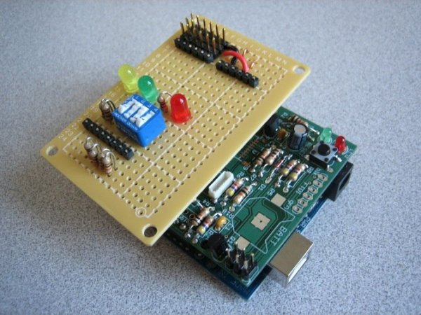
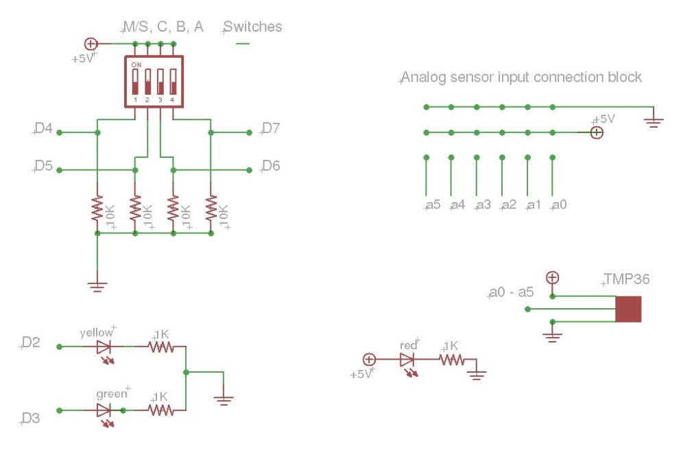
Attached to the top of the GPS shield is a homebrew user interface shield that allows logging interval input, user feedback LEDs and connections for the sensors.
The sensors used are TMP36 from Analog Devices in a TO-92 package but any sensors that can be attached to an Arduino could be used.
Software
The HexiLogger software consists of the following:
– Fat16 Libraries
– User interface supporting code
– Sensor support
Several libraries exist for Arduino/Fat16 interaction, and many of them are variations of each other. I tried a couple of different ones and settled on Fat16 because of its straight forward SD card support. Installation of the library is simple, just add it to arduino-0016/hardware/libraries folder and put #include “Fat16.h” and #include “SdCard.h” into the code. HexiLogger routines initializeCard() and writedataToCard() manage the storage file on the SD card.
The user interface switches are read by the HexiLogger function DetermineTimeDelay() which sets the interval that the sensors will be read. displayCardErrorIndicator(), displayRunIndicator() and
displayWriteIndicator() all handle the LED display.
More information about how the input switches are used to set the interval can be found in one of my other projects.
Each type of sensor will need its own software function in order to convert the raw data from the analog inputs into a meaningful value. I have included four, processLM35SensorDegF(), processTMP36SensorDegF(), processTMP36SensorDegC(),
and processPhotoCell() to handle some types of sensors that I used during development.
The HexiLogger hardware consists of the following modules:
– ATmega328 microcontroller on a Diecimila Arduino board.
– AdaFruit GPS shield, minus the GPS module
– Homebrew user interface shield
– Sensors
For more detail: HexiLogger, an Arduino based data logger


