Stepper motors are great for accurate positioning because they move in discrete steps – a feature that makes them very appropriate for CNC software control. But every once in a while you have an application where you need to press a button and rotate some kind of a jig at a preset angle or move something a preset distance if it’s a stepper-driven linear stage. So, I decided to modify an earlier Arduino sketch I wrote for testing the world’s smallest stepper motor to make it a bit more useful (and clean any bugs in the process). Keep reading to see what came out …
Shout outs to forum user Yellow who in this thread provided an inspiration for the code modification. I had another project in mind but was dragging my foot for a long time, and seeing that someone else can also use results of your work provides a great motivation, so thanks, Yellow!
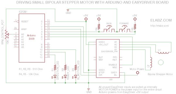
Arduino sketch for the manual EasyDriver control of bipolar stepper motors
Also see the code in the post below. The circuit is extremely simple because most of the hard work of commutating the windings of the stepper is done by the Allegro A3967 motor controller chip, mounted on the EasyDriver board. The Arduino can be any incarnation thereof. I used Nano and I had to move the outputs away from the D0 and D1 because it was messing with uploads (I think it’s only a problem with Nano specifically) but any Arduino will do – there are only 8 digital I/Os and one analog.
The parts list for the project is very short:
-
- Arduino. Any type will be adequate.
- EasyDriver board, populated. Please check with the author, Brian Schmalz on the best source of them.
- Bipolar stepper motor i.e. one with 4 leads. 6- and 8-lead unipolar stepper can also be converted to bipolar by connecting the proper ends of the windings together and floating the center point – not a very difficult task but outside of the scope of this post
- 2 x pushbuttons for LEFT/RIGH a.k.a. UP/DOWN a.k.a CW/CCW control
- 3 x LED for indicators, preferably different color
- 3 x 510 Ohm current limiting resistors for the LEDs
- 2 x 10K Ohm pullup resistors for the buttons
- 1 x 10K Ohm potentiometer (anything between 1K and 100K is fine)
Couple of lines in the Arduino code you may want to look at and adjust to your needs are highlighted in the code below.
Note the int stepsPassedMax = 160; line (line 28).Here 160 means 20 full steps in 1/8th microstepping mode. It just happens that the micro stepper I was using earlier (not the one on the video) had 20 SPR (Steps Per Revolution) and this would have been one 360 degree rotation of the motor’s shaft. If you have a better stepper (200SPR is common), it may only be 1/10th of one rotation – check with the datahseet on the motor and adjust the stepsPassedMax accordingly or send, say, 200*8= 1600 steps and see if the motor completes a full 360 degree revolution if you don’t have a datasheet and suspect that this is a 200SPR motor.
Another adjustment you may make is the desired RPMs or, more appropriately, angular speed since you may not even need a full rotation, hence no R in RPM:
For more detail: Manually controlling bipolar stepper motor with Arduino and EasyDriver