Unhappy with a headlight modulator I purchased, I decided to make my own. Even though it would be a trivial programming project to use an Arduino Teensy or similar to do this, I decided to do it the “old fashioned” way, using a 555 timer. The 555 is a clever chip; not only will it supply the oscillator for the flashing effect, it has a reset pin that can be used to force the output to a known state (low) when (other circuitry tells it that) it’s dark outside. Thus the headlight will be steady “on” after dark, flashing in daylight. The 555 is happy to run directly off the nominal 12 volt vehicle electrical system, so no voltage regulator is needed. The 555 is almost immune to electrical system noise, so no worries about your Arduino code going off into the weeds if there’s a spike from the electrical system.
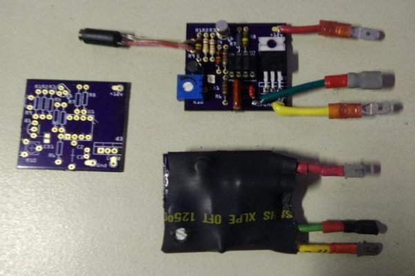
The first photo shows three boards from OSH Park; one bare (as it comes from OSH Park), one stuffed, and one stuffed and covered in heat shrink for installation on my motorcycle (inside a fairing). These are an earlier revision that lacks R11 and R12.
Note: Click on the pictures to embiggen.
The boards, bare and assembled. The photo resistor plugs into the black jack (cylinder) connected via the red/brown pair. The jack for the bottom right board is hidden under the heat-shrink.
The photo resistor assembly
I designed the circuit on the breadboard, and then documented it using fritzing.
Circuit Description:
Note: this circuit is for a DC, negative ground motorcycle. This shouldn’t be a problem, most of you have probably never seen a positive ground motorcycle, but in general, beware British motorcycles made before about 1980, and also some (again, old) motorcycles and scooters had AC lighting systems, and they won’t work with this either.
The 555 is configured as a “nearly” square wave oscillator, with R7, R8, and C2 controlling the frequency. The frequency must be about 240 +/- 40 cycles per minute, or about 4 Hz according to the US law governing headlight modulators. The reason that the output isn’t a perfect square wave is that the charge current for C2 is through R7 and R8, but the discharge current is only through R8, so C2 discharges faster than it charges. The closest to 50% duty cycle will be achieved when R7 is small compared to R8, but if R7 is too small, then R8 will pull too much current from the power rail when it’s discharging C2. 3.9KΩ vs 150KΩ says that the duty cycle error only amounts to 2.5 percent, so duty cycle is close enough to 50% for this application.
Pin 5 of the 555 allows modulating the 555, and we don’t need that, so we just hang a 10nF cap on pin 5 as recommended by the data sheet.
The output of the 555 isn’t robust enough to drive a headlight, so we use a P-MOSFET (Q3) to do the switching. The chosen MOSFET has an RDSon of 0.02 Ω or 20 milliohms, so it barely gets warm powering a 5A headlight filament. It also has a max drain current (Id) of 52 Amps, so it’ll handle pretty much any headlight you care to use on a motorcycle. (Power = I squared R, so for the MOSFET is 25 * 0.02 = .5 watt, which results in negligable heating for a TO-220 package.)
R12 is there to prevent parasitic oscillations by Q3.
The rest of the circuitry is there to sense daylight and switch the modulator to “constant on” when the sun isn’t out.
R9 is a cadmium sulfide photo resistor. I have some old ones in my junkbox, I used those. The resistance on these varies from a few hundred ohms in bright light to a hundreds of thousands of ohms when dark. Pin 4, the reset pin of the 555 timer, needs to be high to allow the 555 to oscillate, or low to force the 555 output (pin 3) to be low (0V).
We can’t just hook the photo resistor (R9) between pin 4 and battery, because there is a particular set of voltages on pin 4 where the 555 output will stay high, which would mean the headlight would be off. This means that if lighting conditions were just right, the headlight would go entirely dark! So we have to prevent pin 4 from ever staying in this “no man’s land”; it must either be at battery voltage or at zero volts.
Q1 and Q2 make up a schmitt trigger (or an amplifier with hysteresis). This means that, as the input voltage changes, the amplifier output will “snap” past a region of middle voltages, both as the voltage rises and as it falls.
You can use any small signal BJTs for Q1 and Q2; I just used what I had in my junkbox. As long as the BVceo is greater than 16 volts (max volts expected from automotive charging system) any decent NPN (Q1) and PNP (Q2) transistors should be fine. The choice for Q3, an IRF4905, is critical; it needs to be carry current of 5 or more amps, and it needs to have a very low Rds-on so it doesn’t get hot. These are cheap, however, and readily available (I bought mine on eBay). Do not substitute another MOSFET unless you find one with a lower RDSon value.
Read more: Headlight Modulator for Motorcycle