
Summary of Head Mouse With MPU6050 and Arduino Micro
This article details a DIY "Head Mouse" project that converts head movements into cursor control using an Arduino Micro and an MPU6050 accelerometer/gyroscope. The creator built upon Martin Millmore's existing design, utilizing a Compeed box for housing and elastic bands for wearing. The guide covers hardware assembly, soldering connections, and software configuration, offering three code variations: standard movement, testing output, and a version with a delayed click feature triggered by holding the cursor in a specific zone.
Parts used in the Head Mouse:
- Arduino Micro
- Accelerometer/gyroscope MPU6050
- Compeed box
- Elastic band
- Micro USB cable to USB type B
- Cables
- PCB board
- Glue or Sugru
Hi everyone, here it is my new project, a mouse controlled with the movement of the head!
I decided to make this project once I received my accelerometer/gyroscope MPU6050 from IC Station, and I wanted to do something useful with this.
Then I found out that a “Head Mouse” already exists, made by Martin Millmore with another accelerometer/gyroscope: https://www.instructables.com/id/Head-Mouse-Game-controller-or-disability-aid/
Well here it is my version, made with an Arduino Micro and a MPU6050.
Thanks to IC Station http://www.icstation.com/ for the accelerometer/gyroscope they sent me, allowing me to create this project!
Step 1: Materials and Tools Needed
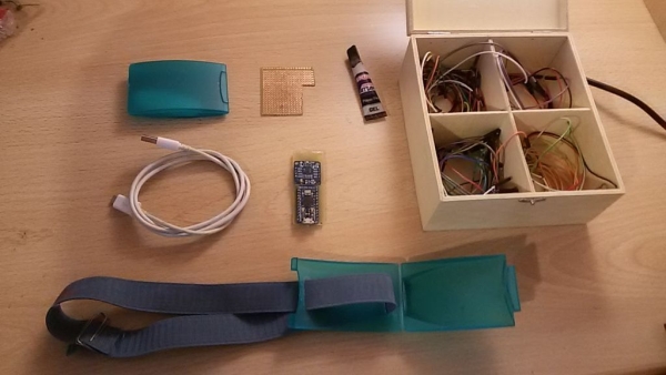
Materials needed:
– Arduino Micro;
– accelerometer/gyroscope MPU6050;
– a Compeed box (I found this comfortable as Martin Millmore said in his guide);
– an elastic band;
– micro USB cable to USB type B (like those used for Android smartphones);
– cables;
– a pcb board;
– glue, or better, Sugru.
Tools needed:
– a computer with the Arduino IDE installed;
– soldering station;
– mini drill.
Step 2: Building
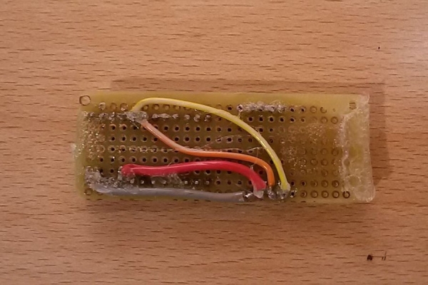
1) Solder on the pcb board the pins like in the image: pin 2 of Arduino to pin SDA, pin 3 to SCL, pin 5V to PWR, pin GND to GND.
2) Make a hole with the dremel on the Compeed box so the micro USB cable can reach the Arduino Micro, and two straight holes for the elastic band.
3) glue the board to the box and add the elastic band.
Step 3: Code
Connect the board to your computer and load first the “Test” code to the Arduino to test if everything work fine. You’ll probably need to change some values (everything is written in the code’s comments) since I had to add a constant, beacuse values from the gyroscope are not “zero” when I’m not moving.
Use the Serial Monitor to check if you need to fix the “zero” of the gyroscope.
Once you found the right values you can load the program deleting the “Serial.print” part, that is equivalent to the standard code.
If you want the click function after a delay of time since the pointer has been in a 10×10 pixel zone load the code “with_click” to Arduino Micro.
Here there are the codes:
– standard code with only movement: https://www.dropbox.com/s/hnrhdtsoqzi8azr/Mouse_Gyro_ENG.ino?dl=0
– code to test the output: https://www.dropbox.com/s/t2f63ichd4g93n1/Mouse_Gyro_TEST_ENG.ino?dl=0
– code with movement and click after 2 seconds: https://www.dropbox.com/s/vdsg8jo1toebt4d/Mouse_Gyro_with_click_ENG.ino?dl=0
To use them you’ll need the MPU6050 and I2C libraries:
MPU 6050: http://arduinomeetslinux.com/download/MPU6050.zip
I2C: http://arduinomeetslinux.com/download/I2Cdev.zip
In this site I found the libraries and the code from which I developed the programs of my project: http://arduinomeetslinux.com/content.php?p=5
Link to Martin Millmore’s project with the LSM9DS0 instead of the MPU6050: https://www.instructables.com/id/Head-Mouse-Game-controller-or-disability-aid/
Source: Head Mouse With MPU6050 and Arduino Micro
- How do I connect the MPU6050 to the Arduino Micro?
Solder pin 2 of the Arduino to SDA, pin 3 to SCL, pin 5V to PWR, and GND to GND on the PCB board. - What is the best way to house the electronics for this project?
Use a Compeed box, drill a hole for the micro USB cable, and create holes for the elastic band. - Can I use the standard code immediately without adjustments?
No, you likely need to adjust values in the code because gyroscope values are not zero when stationary. - How can I test if the sensor is working correctly before final coding?
Load the Test code onto the Arduino and use the Serial Monitor to check the output and fix the zero value. - Does the project support a click function?
Yes, you can load the with_click code to enable a click after the pointer stays in a 10x10 pixel zone for two seconds. - Which libraries are required to run the code?
You need the MPU6050 library and the I2C library from arduinomeetslinux.com. - What tools are necessary to build the physical device?
You need a soldering station and a mini drill to prepare the housing and assemble the components. - Where can I find the source code for this project?
The codes are available via Dropbox links provided in the article for standard, test, and click-enabled versions.
