
Summary of Hard Disk Clock (HDD Clock with Arduino Uno)
This article guides you through building a low-cost Point-of-View (POV) clock using an Arduino Uno and a repurposed hard disk drive motor. The project involves modifying a hard disk to create a slot for the visual effect, mounting an RGB LED strip, and integrating sensors like a photodiode and IR transistor to synchronize the display with the rotating disk. Users can control time settings and colors via pushbuttons or a remote controller, while a temperature sensor adds extra functionality.
Parts used in the Hard Disk Clock:
- Arduino Uno
- RTC modul
- ULN 2003
- IR diode
- IR transistor
- 4 pushbuttons
- TSOP4838
- Temperature sensor (DS18B20)
- RGB led strip
- Connectors
- Paper
- Old hard disk with working motor
This is a fun project that can be done easily and also cheaply. In this instructable we will explain step by step how to make this beautiful POV clock.
Used material:
- Arduino Uno,
- RTC modul,
- ULN 2003,
- IR diode and IR transistor (used like a sensor, more details in next steps)
- 4 pushbuttons (for controling the clock)
- TSOP4838 (allows us to control the clock with remote controler)
- Temperature sensor (DS18B20)
- RGB led strip
- Connectors,
- Paper,
- And of course and old hard disk with working motor.
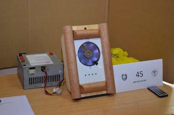
Step 1: Begining (Disk, RGB, Sensor)
Before you put the disk back on the motor you shuold mount RGB strip and sensor. Also i noticed that you can better see the time on clock when there is the white backgroud behind the disk.Take a sheet of paper and use one removed disc of the Hard drive to draw a circle. This should help you cut paper precisely. When you do that glue the paper for hard disk
For this clock we have used the photodiode and phototransistor as a sensor. Such a sensor with casing can be found in the printer, so we got one of those from an old printer.The role of the sensor in this clock is to tell microcontroller in which the position cut made on disk is.That way he is able to show time. You should use three wires and solder them for those 3 pins of the sensor.
You have to mount the sensor on the little white fellow marked red on the Fig 5 because the program is made for that position. And to be realistic, this is the easiest place to put him.
Now you can put the disk back.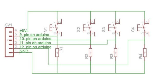
Step 2: It’s time to build
So in this step you can download eagle files with PCB. This boards are going to be places up front. One of them is used for powering the sensor and RGB strip. Second board is used for controling the clock with pushbuttons.
First pushbutton is used for entering the programing mode of the clock. After we activate it we can change hours (second pushbutton) and minutes (third pushbutton). When we want to change color of the clocks hand we use fourth pushbutton. Then with second pushbutton we can change color and with third the hand of the clock that we want to change.
You can see how to connect this boards in the eagle files.
For more detail: Hard Disk Clock (HDD Clock with Arduino Uno)
- How do I create the cut on the hard disk?
You should use a CNC machine or a grinder to make a cut on one of the disks, leaving a few inches uncut. - What is the role of the sensor in this clock?
The sensor tells the microcontroller which position the cut on the disk is in so it can show the correct time. - Where can I find the photodiode and phototransistor?
Such a sensor with a casing can be found inside an old printer. - Can I control the clock with a remote?
Yes, the TSOP4838 component allows you to control the clock with a remote controller. - What does the first pushbutton do?
The first pushbutton is used for entering the programming mode of the clock. - How do I change the color of the clock hand?
You use the fourth pushbutton to change the color, then the second button to select the specific color. - Why is a white background recommended?
A white background behind the disk helps you see the time better on the clock. - What are the two PCB boards used for?
One board powers the sensor and RGB strip, while the second board controls the clock with pushbuttons. - How do I set the minutes on the clock?
After entering programming mode, you use the third pushbutton to change the minutes. - Do I need to remove the disks from the motor?
Yes, you must remove the disks from the motor with a screwdriver before starting the build.
