Summary of Gyro Camera for Motorcycle using Arduino
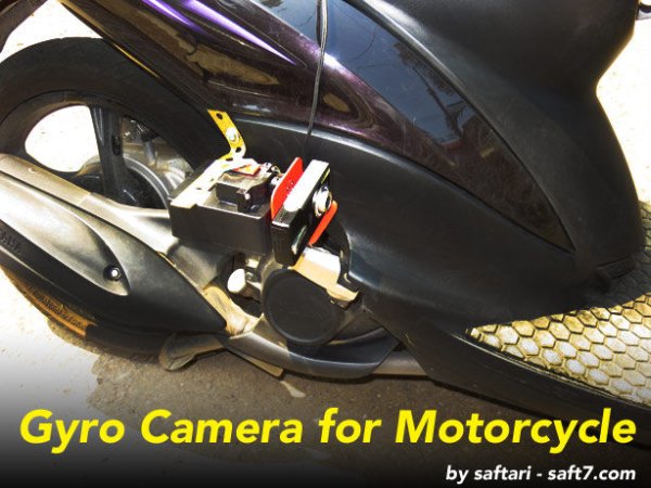
This article explains how to build a gyro-stabilized camera for motorcycles, mimicking MotoGP footage where the view remains level despite the bike leaning. The project uses an MPU-6050 sensor module with an Arduino Uno R3 and a digital servo. By combining gyroscope and accelerometer data via a Kalman Filter, the system smooths out noise to keep the camera horizontally aligned while the motorcycle tilts during turns.
Parts used in Gyro Camera for Motorcycle:
- Triple Axis Accelerometer & Gyro Breakout – MPU-6050
- Arduino UNO R3
- Digital Servo
- Breadboard Mini
- 9v Battery + Switch
- Box and other accessories
As seen in MotoGP Race, the rider is seen riding through corners while laying aside his bike to the left and right. But there is an interesting moment when the motor looks to collapse sideward, the front views remain horizontally. How could that be?
Such onboard camera applies GYRO system, where the camera will be fixed perpendicular to the gravity of the earth.
Step 1: BUILD YOUR OWN GYRO CAMERA
We could build our own Gyro Camera by using GYRO and ACCELEROMETER modules.
They are two separate modules, hence we have to use two modules simultaneously. Then we make Gyro Chip and Accelerometer Chip in one module (there are two chips in one module). In latest version they are made in one chip only, thus minimizing the distortion of movement calculation
In this article, the module is Triple Axis Accelerometer & Gyro Breakout – MPU-6050, which has 3-axis gyroscope and 3-axis accelerometer in one chip, supplied by power of 3.3volt.
In addition to module MPU6050, the following similar modules could also be applied:
• IMU Fusion Board – ADXL345 & IMU3000
• IMU Digital Combo Board – 6 Degrees of Freedom ITG3200/ADXL345
Module MPU6050 with its tiny size of 20mm x 15mm and height of 1.6mm.
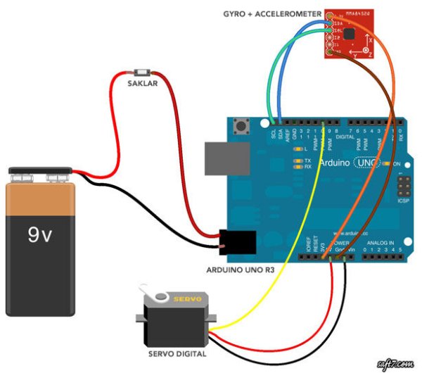
If you using different board than Arduino Uno R3, SCL and SDA pins of MPU are also different:
VDD : +3.3V
VIO : +3.3V
GND : GND
SDA : Pin A4 (Arduino Uno, Ethernet) / Pin 20 (Mega2560, Due) / Pin 2 (Leonardo)
SCL : Pin A5 (Arduino Uno, Ethernet) / Pin 21 (Mega2560, Due) / Pin 3 (Leonardo)
Step 2: PROGRAMMING
After having completely assembled, it is time now to upload the program to Arduino.
This circuit is only to drive servo in axis-X only. However, data from Axis Y and Z are still required for the respective Gyroscope and Accelerometer. I tried to combine them by applying Kalman Filter calculation so as to reduce ‘noise’ output from Gyroscope + Accelerometer so that servo movement is smooth and no unwanted movement.
CODE:
/*
GYRO CAMERA - saft7.com

Demonstrates auto-leveling Camera Video by using Gyro & Accelerometer with Arduino

The circuit:
Servo controlled by Arduino, using Gyro and Accelerometer as reference of movement.

Created March 12, 2013
by Firmansyah Saftari
www.saft7.com

This code and complete article can be found at:

http://www.saft7.com/

Programming Language: C++

*/

#include <Servo.h>
Servo xservo;

#include <Wire.h>
#include "Kalman.h"
Kalman kalmanX;
Kalman kalmanY;

uint8_t IMUAddress = 0x68; // MPU6050 Address
• Triple Axis Accelerometer & Gyro Breakout – MPU-6050
• Arduino UNO R3
• Digital Servo (use good and powerful servo)
• Breadboard Mini
• 9v Battery + Switch
• Box and other accessories.
For more detail: Gyro Camera for Motorcycle using Arduino
- How does the onboard camera maintain a horizontal view?
The camera applies a GYRO system fixed perpendicular to the gravity of the earth. - Can separate modules be used instead of one chip?
Yes, two separate modules can be used simultaneously, though latest versions combine them into one chip to minimize distortion. - What voltage powers the MPU-6050 module?
The module is supplied by power of 3.3volt. - Which pins connect SDA and SCL on an Arduino Uno?
SDA connects to Pin A4 and SCL connects to Pin A5. - Does the circuit drive servos on all axes?
No, this circuit is only to drive servo in axis-X only. - Why is a Kalman Filter calculation applied?
It is applied to reduce noise output from the Gyroscope and Accelerometer so servo movement is smooth. - What programming language is used for the code?
The programming language used is C++. - Are there alternative modules to the MPU-6050?
Yes, similar modules include IMU Fusion Board ADXL345 & IMU3000 and IMU Digital Combo Board 6 Degrees of Freedom ITG3200/ADXL345.