Summary of Grab Control of Industrial Automation with This DIY Joystick System
This article details a remote control system for up to four industrial devices using an Arduino Nano and a joystick. The setup maps joystick movements in X and Y directions to activate specific relays, enabling simultaneous operation of motors, pumps, or solenoids. The system utilizes a 7805 voltage regulator for stable power, NPN transistors as switching elements, and a full-wave rectifier circuit. It offers a simple interface for industrial automation by converting analog joystick signals into digital relay commands.
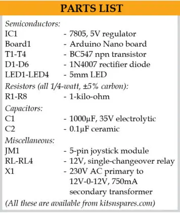
Parts used in the Joystick-Controlled Industrial Automation System:
- Arduino Nano microcontroller board
- Joystick module with X and Y axes
- 4 industrial appliances (motors, pumps, solenoids)
- Relay modules (12V single-pole single-throw)
- 7805 5V voltage regulator IC
- Step-down transformer (230V AC to 12V-0-12V)
- NPN transistors (T1 through T4)
- Rectifier diodes (1N4007 type)
- Smoothing capacitors
- Flywheel diode (D3)
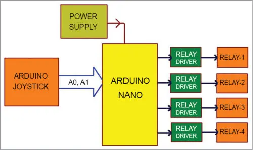
This system allows remote control of up to four industrial devices using a joystick and Arduino Nano microcontroller board. Figure 1 presents a block diagram of the joystick-controlled industrial automation setup.
Key components include:
An Arduino Nano which processes signals from the joystick and outputs control commands.
A joystick module that generates analog position readings for the Arduino to interpret as movement commands.
Up to four industrial appliances/machines that can be selectively activated based on joystick position, such as motors, pumps, solenoids etc.
Relay modules to switch high-voltage/current loads under command of the Arduino’s low-power outputs.
The Arduino reads the joystick and maps positions to commands for individual relays connected to each appliance. This provides a simple interface for operating multiple industrial systems simultaneously from a single joystick control station.
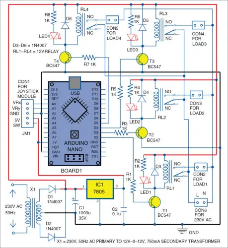
The electrical schematic for the joystick control system is presented in Figure 2. At its core is an Arduino Nano microcontroller board (Board 1) which oversees operation.
A 7805 5V voltage regulator IC (IC1) steps down power from a wall adapter transformer (X1) to stable 5V for the Arduino circuitry.
Four NPN transistors (T1 through T4) act as switching elements, each controlling one relay through the Arduino.
A joystick module (JM1) provides analog position readings to the microcontroller.
Four 12V single-pole single-throw relays (RL1 through RL4) handle remote switching of high-voltage appliances.
Together, these components enable the Arduino to monitor joystick movement and selectively energize the relay coils, thus allowing control of separate loads from the single joystick interface. The regulator, transistors and relays safely interface the low-voltage control signals to industrial equipment.
Joystick module
Joysticks come in various physical forms. A common joystick module is pictured in Figure 3. This type of joystick module produces analog voltage signals that vary based on shaft position.
Specifically, as the joystick shaft is moved in different directions, the corresponding output voltage changes. By reading these voltage levels with a microcontroller, the direction of joystick movement can be interpreted programmatically.
For example, pushing the shaft fully forward may output 3.3V on one pin and 0V on another, indicating forward motion. Releasing the shaft returns it to the center position with voltages around 1.65V on both pins.
This analog position encoding allows a microcontroller to continuously monitor joystick deflection without mechanical switches. It can then initiate appropriate control actions based on decoded motion directions from the variable voltage outputs.
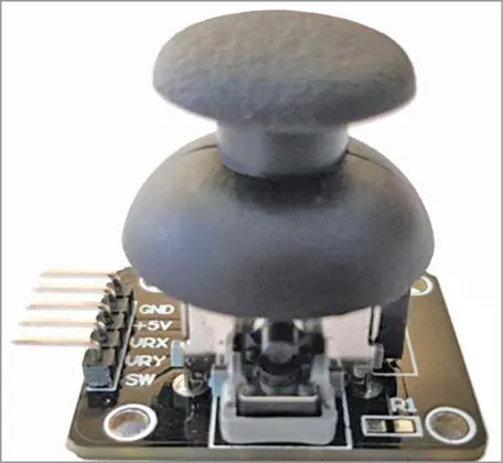
This joystick module contains two axes of control – X and Y. Each axis has a potentiometer whose shaft position controls the associated voltage level.
Specifically, the potentiometers’ wiper outputs – labeled VRx and VRy at connector CON1 – act as voltage dividers whose values vary with shaft position. VRx responds to horizontal (left-right) movements while VRy reacts to vertical (up-down) motions.
Therefore, the four possible combinations of shaft positions along the two axes produce distinct voltage readings on the VRx and VRy pins. These analog signals connect to the Arduino Nano’s two ADC input pins A0 and A1 for digitization.
By monitoring the voltage levels, the Arduino can determine joystick direction. Pushing the shaft in a given direction causes one pin voltage to rise while the other falls. An additional button is included but not utilized here.
As illustrated in Figure 2, the joystick module interfaces with the Arduino’s ADC inputs. The microcontroller then outputs signals through pins D2 to D5 to control four relays (RL1 to RL4) for selective actuation of loads.
Power supply
The power supply circuit utilizes a full-wave rectifier design to provide the necessary voltage levels. It contains:
A step-down transformer (X1) rated at 230V AC primary to 12V-0-12V, 750mA on the secondary side.
Rectifier diodes D1 and D2 (1N4007 type) which convert the AC to pulsating DC.
Smoothing capacitors C1 and C2 that filter the rectified voltage into a stable DC output.
Voltage regulator IC1 (7805 type) that takes the raw 12V and regulates it down to a clean 5V supply.
This circuit design addresses the two voltage requirements. The 12V DC output after rectification and filtering powers the relay coils. Meanwhile, the 5V rail regulated by IC1 is used to operate the Arduino Nano microcontroller board.
By stepping down mains AC and employing rectification, regulation and filtering stages, the power supply generates the appropriate DC levels necessary to interface the low-voltage microcontroller with high-current industrial relay loads.
Arduino Nano
The Arduino Nano is a compact microcontroller board compatible with the ATMega328 chip. Its key specifications include:
Logic level and recommended operating voltage of 5V and 7V-12V input range respectively.
Broad 6V-20V input voltage tolerance limits.
Fourteen digital pins capable of input/output, of which six provide Pulse Width Modulation (PWM) output.
Eight analog input pins for reading variable voltages.
Pin current rating of 40mA to safely interface actuators and sensors.
32kB flash memory with 30kB available for code after reserving 2kB for the bootloader.
2kB SRAM and 1kB EEPROM for data storage.
16MHz clock speed for acceptable processing performance.
These specs allow the Arduino Nano to reliably interface with various peripherals and sensors while running user programs to control industrial automation systems.
Operation
In the centered, neutral position of the joystick module, the digital readings for the VRx and VRy analogue outputs will both be 512.
This is because the Arduino Nano has a 10-bit analog-to-digital converter (ADC), which maps the analogue voltages to integer digital values ranging from 0 to 1023.
At the midpoint voltage level when the joystick is untouched, which represents the idle or standby mode, the ADC correctly converts this voltage to the middle digital code of 512.
So when monitoring the ADC inputs connected to VRx and VRy, a reading of 512 on both channels indicates the joystick is in the zeroed-out center position with no movement registered along either axis. This baseline value allows software to detect any deflection from neutral.
Case 1
Moving the joystick shaft left along the x-axis causes the digital value from the VRx input to drop below 50.
The program code detects this condition and sets the Arduino’s pin D2 to HIGH. This forward biases the base-emitter junction of transistor T1, switching it to the ON state.
With T1 conducting, current flows through relay RL1’s coil, activating the switching contacts. As a result, the load device wired to RL1 receives power and turns on.
Diode D3 acts as a flywheel diode, providing a path for the back EMF created when the relay coil is de-energized to ensure proper switching without damage to the transistor.
In summary, left joystick movement elicits a response from the microcontroller to energize RL1 via T1, enabling remote control of the specific load through positional input on the x-axis.
Case 2
If the joystick shaft is moved right along the x-axis, the digital reading from the VRx input will exceed 900.
The program detects when the value surpasses this threshold and activates Arduino pin D3, switching it high.
This forward biases the base of transistor T2, facilitating current flow through its collector-emitter path.
As a result, relay RL2’s coil is energized via transistor T2. The activated relay contacts then power on the electrical load connected to RL2.
In essence, by moving the joystick right, the microcontroller triggers transistor T2 and relay RL2 to remotely toggle the state of the corresponding device. The positional control along the x-axis is thus implemented through intuitive joystick deflection.
Case 3
If the joystick shaft is pushed down along the y-axis, the digital reading from the VRy input will drop below 50.
When this condition occurs where the value is less than 50, the program sets Arduino pin D4 high.
This forward biases transistor T3, allowing current to flow through its collector and emitter path. As a result, relay RL3’s coil is activated via T3.
With the relay coil now energized, the contacts switch to power on the load device wired to RL3.
In essence, downward movement along the y-axis triggers the microcontroller to energize transistor T3 and relay RL3, toggling the respective electrical appliance on remotely. This realizes real-time control based on vertical joystick deflection.
Case 4
If the joystick shaft moves up along the y-axis, the digital reading from the VRy input will exceed 900.
When the value registers above 900, the program turns on Arduino pin D5. This forward biases transistor T4, enabling current to pass through its collector and emitter terminals.
Energization of transistor T4 subsequently activates relay RL4’s coil. With the relay now powered, its contacts switch to deliver power to the load wired to RL4.
In summary, upward movement along the y-axis prompts the microcontroller to trigger transistor T4 and relay RL4, thereby remotely controlling the associated industrial device. The system thus provides functional vertical movement control via the joystick.
Software program
The core functionality is implemented through software loaded onto the Arduino Nano’s onboard memory. The program is written in the Arduino programming language, commonly called a sketch.
The Arduino IDE version 1.6.8 is used to compile and transfer this sketch to the microcontroller. The ATmega328P chip features a pre-installed bootloader that allows uploading new code without an external programmer.
To run the program, the Nano board connects to a PC via USB. The correct COM port is selected in the IDE. The sketch named “joystick_control.ino” is compiled then uploaded, selecting the matching Nano board from the Tools menu.
This loads the sketch into the MCU’s memory, where it oversees all primary operations. In this simple project, external libraries are unnecessary – the sketch directly reads joystick values, compares the VRx and VRy readings using if/else logic, and controls the four appliances accordingly.
The uploaded sketch is thus the driving force behind bringing the hardware system to life through software control of the joystick interface and relays.
Construction and testing
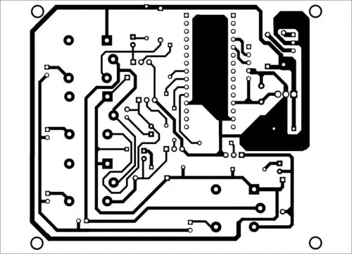
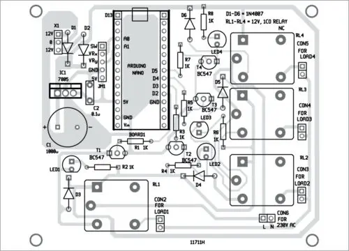
Figures 4 and 5 depict the printed circuit board (PCB) layout design and component placement diagram for the physical joystick control system.
To construct the system, first connect the transformer power output wires to the board’s terminals labeled X1. Then attach the joystick module’s signal wires to the header JM1.
Once the programming sketch has been uploaded as previously explained, mount the Arduino Nano onto the PCB in the designated space. Switch on the power supply to energize the board.
From this point, the operator can test bidirectional control by deflecting the joystick shaft left, right, up and down. This positional input will actuate the intended electrical loads remotely.
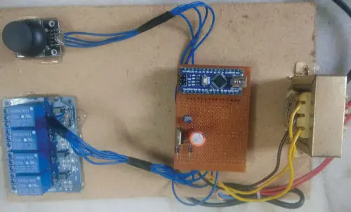
Figure 6 shows the author’s realized prototype of this joystick-controlled automation system assembled on the PCB according to the layout designs. By following the schematic and board designs, one could replicate this proof-of-concept demonstration of industrial remote selection via an intuitive joystick interface.
- How many industrial devices can this system control?
The system allows remote control of up to four industrial devices. - What component processes signals from the joystick?
An Arduino Nano microcontroller board processes the signals and outputs control commands. - Does the joystick module use digital or analog signals?
The joystick module produces analog voltage signals that vary based on shaft position. - How does the power supply generate the required voltages?
It uses a step-down transformer, rectifier diodes, smoothing capacitors, and a 7805 voltage regulator to create 12V and 5V DC outputs. - What happens when the joystick is moved left along the x-axis?
The digital value drops below 50, activating pin D2, transistor T1, and relay RL1 to turn on the first load. - Can the system operate multiple loads simultaneously?
Yes, it provides a simple interface for operating multiple industrial systems simultaneously from a single joystick control station. - What software environment is used to program the Arduino?
The Arduino IDE version 1.6.8 is used to compile and upload the sketch named joystick_control.ino. - What are the threshold values for detecting rightward movement?
Moving the joystick right causes the digital reading from the VRx input to exceed 900. - What is the purpose of the flywheel diode D3?
Diode D3 acts as a flywheel diode to provide a path for back EMF created when the relay coil is de-energized.