Summary of Getting Started With the ESP8266 ESP-01
This tutorial guides users through setting up the ESP8266 ESP-01 Wi-Fi module to enable microcontroller internet connectivity or to act as a standalone microcontroller. It covers hardware connections with an Arduino UNO, verifies functionality using AT commands, and demonstrates how to switch between operation modes (Access Point, Station, or both). The tutorial also details connecting to Wi-Fi, enabling multiple connections, setting up a server, and sending/receiving data through HTTP requests, providing a foundational understanding of communicating with the ESP-01 module.
Parts used in the ESP8266 ESP-01 Wi-Fi Module Setup:
- ESP8266 Wi-Fi Module ESP-01
- Male/female jumper wires
- Breadboard
- Arduino UNO
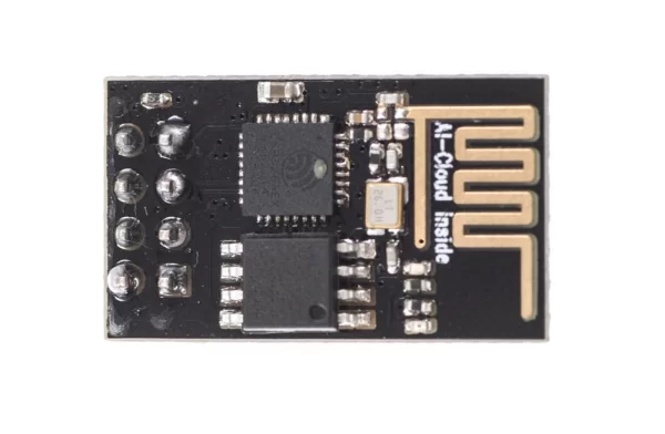
The ESP8266 ESP-01 is a module for Wi-Fi that enables microcontrollers to connect to a Wi-Fi network. This module is an independent SOC (System On a Chip) that does not require a microcontroller for managing inputs and outputs like you would typically do with an Arduino, as the ESP-01 functions as a miniature computer. It is possible to have a maximum of 9 GPIOs on the ESP8266, depending on the version. Hence, we can enable a microcontroller to connect to the internet similar to the Wi-Fi shield enabling the Arduino, or we can code the ESP8266 to not just connect to a Wi-Fi network, but also function as a microcontroller. This feature gives the ESP8266 a lot of flexibility, potentially reducing costs and saving space in your projects.
This tutorial will demonstrate the process of setting up the ESP-01 Wi-Fi module, configuring it, and ensuring communication with another device is successful.
Step 1: Materials
These are the components that you will need:
Step 2: ESP-01 Setup
When purchasing the ESP8266 ESP-01, it comes with AT firmware already installed. It is feasible to reprogram the chip with alternative firmware like NodeMCU, for instance. Nonetheless, the AT firmware works with the Arduino IDE, making it the firmware choice for this tutorial. To learn how to install an alternative firmware, refer to the Miscellaneous section in this guide.
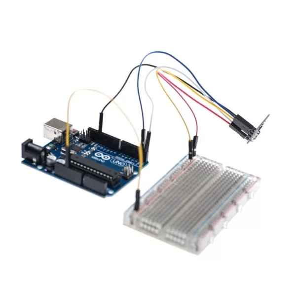
Begin by using the jumper wires to link the Wi-Fi module to the Arduino as demonstrated in the provided pictures.
Step 3: ESP-01 Setup Continued
Upload the BareMinimum example to ensure that no previous programs are running and using the serial communication channel. Next, open the serial monitor and type the following command:
AT
You should get an “OK” response. This means that the module is working and that you are good to go. Now we are ready to test a two way communication between the module and another device.
Step 4: Basic AT Commands
The ESP8266 ESP-01 module has three operation modes:
- Access Point (AP)
- Station (STA)
- Both
The Wi-Fi module in Access Point (AP) functions as a Wi-Fi network, enabling other devices to link up to it. This doesn’t imply that you can access your Facebook through your device when the ESP-01 module is in AP mode. It creates a two way communication link between the ESP8266 and the connected device through Wi-Fi.
When operating in STA mode, the ESP-01 has the ability to link up with an Access Point like the Wi-Fi network at your residence. This enables every device on the network to interact with the module.
The module can function as both an AP and a STA in the third operating mode.
Step 5: Basic AT Commands – STA Mode
In this tutorial, we are going to set the module to operate in STA mode by typing the following command:
AT+CWMODE=1
The corresponding number for each mode of operation is as follows:
- STA = 1
- AP = 2
- Both = 3
Step 6: Basic AT Commands – Check Mode
If you want to check what mode your Wi-Fi module is in, you can simply type the following command:
AT+CWMODE?
This will display a number (1, 2, or 3) associated with the corresponding mode of operation.
Step 7: Basic AT Commands – Connecting Wi-Fi Network
Once we have the ESP-01 operating in STA mode, we need to connect to a Wi-Fi network. First we can check if we are already connected to one by sending the command:
AT+CIFSR
This will display the station IP address of our ESP-01 module. If you don’t get an IP address after entering the previous command, use the following command to connect to your network:
AT+CWJAP= “Wi-FiNetwork”,“Password”
Type the name of your Wi-Fi network and the password to connect to it. Make sure you include the quotation marks. After a couple of seconds, you should get an “OK” response. You can check again to see if you have an IP address using the AT+CIFSR command.
Step 8: Basic AT Commands – Enable Connections
Then we need to enable multiple connections before we can configure the ESP8266 ESP-01 module as a server. Type the next command:
AT+CIPMUX=1
Once again, each number is associated with a type of connection:
- Single = 0
- Multiple = 1
The following step is to start the server at port 80:
AT+CIPSERVER=1,80
The first number is used to indicate whether we want to close server mode (0), or open server mode (1). The second number indicates the port that the client uses to connect to a server. We chose port 80 because this is the default port for HTTP protocol.
Step 9: Basic at Commands – Response
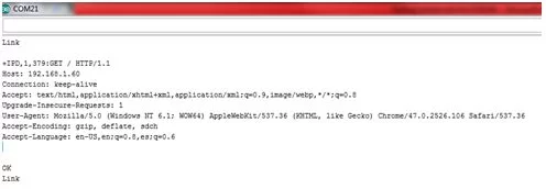
Now, when we open a web browser and type the IP address of our ESP module we get the following response as shown in the image above.
This is the HTTP request that our computer sends to the server to fetch a file. It contains some interesting information such as what file you want to retrieve, name of the browser and version, what operating system you are using, what language you prefer to receive the file in, and more.
Step 10: Basic AT Commands – Send and Display Data
We can now use the following commands to send some data and display it in our web browser’s window:
AT+CIPSEND=0,5
The “0” indicates the channel through which the data is going to be transferred; while “5” represents the number of characters that are going to be sent.
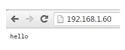
When we hit enter, the symbol “>” appears. This indicates that we can now type the characters that we want to send to the browser. In this example we chose “hello.”
After a couple of seconds we get the response “SEND OK.” This means that the data has been transmitted successfully to the client. However, nothing appears on the web browser’s window yet. This is because it is required to close the channel first in order to display the characters. We use the following command to close the channel:
AT+CIPCLOSE=0
“0” indicates the channel that is being closed.
Once we hit enter, our message is displayed on the web browser’s window as shown in the image above.
You can refer to the following site to see the ESP8266 AT Command Set:
http://www.pridopia.co.uk/pi-doc/ESP8266ATCommands…
Read more: Getting Started With the ESP8266 ESP-01