
Summary of General Instruments SP0256-AL2 English Phoneme Speech chip & an Arduino
This article details reviving a vintage GI SP0256 speech synthesizer chip using an Arduino. The author explores hardware simplifications, such as replacing the original crystal oscillator with a timer-generated square wave and controlling reset signals via GPIO instead of analog circuits. The project successfully demonstrates that complex 1980s components can be interfaced with modern microcontrollers using minimal external parts, though some phonemes may feel limited compared to modern standards.
Parts used in the GI SP0256 Speech Synthesizer Project:
- GI SP0256 chip (AL2 variant)
- Atmel-based Arduino board
- 3.28 MHz crystal (alternative to original 3.14 MHz)
- 33KOhm resistor
- 0.22uF capacitor
- Koss Ur/29 headphone (used as speaker)
The GI SP0256 chip is an early 1980s bit of technology. It’s a 5V (to 7V) NMOS chip which is compatible enough with the 5V TTL circuity common in that era. 5V TTL disappeared for a while, then came back with the Atmel _28-based Arduino boards, many of which run at 5V.
The SP0256 chip contains a [crude] electronic model of the human voicebox, and the -AL2 variant comes with 59 English language phonemes built into it. In theory that ought to be sufficient, though in practice perhaps a few more (like an EEEEE sound like in “E.T. the extra-terrestrial”) seem to be needed. Anyway the manufacturer isn’t going to update this part .
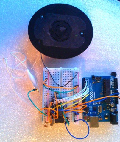
Sound
Listen to what it sounds like:
Right-click and download if it doesn’t play in your browser.
Story
When looking through a box of parts I came across this big chip I vaguely remembered buying as a teenager after reading an article in some 8-bit Atari centric home computing magazine. Maybe this was the article Cheep Talk – Build Your Own Speech Synthesizer in the April 1985 issue of Analog Computing, or this article Talking Typewriter in the January 1987 issue of Antic Magazine, or maybe a handout from Radio Shack. I think I built the circuit and played around with it because the chip’s sound was familiar. Anyway now, in 2014, the chip was there, alone, stuck into the far end of a breadboard for safekeeping.
With the help of the internet for the SP0256 Datasheet and example circuit diagrams and an arduino to drive it it was time for the ole chip to talk again.
There isn’t anything very complicated about using the SP0256. In fact the circuit is tolerant of a lot of Muntzing.
- The 3.14 MHz crystal was hard to find in 1985, and is impossible now. I found a 3.28 MHz crystal on Mouser and used that. The magazine articles from the 1980s state a common 3.59 MHz crystal works too.
- But really the crystal and occumpanying capacitors are unnecessary. The arduino can be programmed to generate a 16MHz / 6 = 2.66 MHz square wave from a timer, and that can be sent into the OSC1 (pin 27). It turns out 2.6 MHz is close enough for the SP0256. It doesn’t even sound slurred. The #define DRIVE_CLOCK_USING_ATMEL enables this feature in the source code.
- The better example circuits have a diode across the resistor in the 0.1uF C + 100KOhm R reset circuit. The diode is there to discharge the capacitor quickly if power drops before the capacitor has discharged through the resistor. This is needed for a reliable reset if power might blip on and then off. Do you need it in a home use test circuit? Nope!
- In fact the whole analog reset circuit is unnecessary. The two reset pins (~RESET and ~SBY_RESET) can be controled from an arduino GPIO. That has the advantage that you reset the SP0256 when the arduino sketch restarts. The #define DRIVE_RESET_USING_ATMEL enabled this feature in the source code.
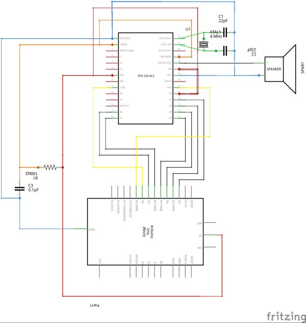
- The input pins float reliably at a low logic level (which must be an NMOS characteristic, since TTL would float high) so you can omit grounding A7 and A8.
- The output low-pass 33KOhm-0.22uF RC filter is unnecessary if you use a speaker with a coil. The inductance of the coil is apparently sufficient. (With a piezo electric speaker, however, no amount of filtering helps, even the two stages of RC filtering one circuit diagram suggests. I used half of a cheap (& broken) Koss Ur/29 headphone
- As an advantage, if you don’t put the output through an RC circuit, it’s already a 5V peak-to-peak signal and opamp amplification stage is unnecessary.
For more detail: General Instruments SP0256-AL2 English Phoneme Speech chip & an Arduino
- What voltage does the GI SP0256 chip require?
The chip operates on 5V to 7V and is compatible with 5V TTL circuitry. - How many English language phonemes are built into the AL2 variant?
The AL2 variant comes with 59 English language phonemes built into it. - Can I replace the original 3.14 MHz crystal with an Arduino generated signal?
Yes, the Arduino can generate a 2.66 MHz square wave which is close enough for the chip to function without sounding slurred. - Is the analog reset circuit necessary for this project?
No, the analog reset circuit is unnecessary because the reset pins can be controlled directly from an Arduino GPIO. - Do I need to ground the A7 and A8 input pins?
No, the input pins float reliably at a low logic level so you can omit grounding them. - What happens if I use a piezo electric speaker instead of a coil speaker?
No amount of filtering helps when using a piezo electric speaker, even with multiple stages of RC filtering. - Is an opamp amplification stage required for the output?
No, if you do not put the output through an RC circuit, it is already a 5V peak-to-peak signal requiring no amplification. - Why was the diode across the resistor in the reset circuit included in older designs?
The diode discharges the capacitor quickly if power drops before the capacitor has discharged through the resistor for a reliable reset.
