Recently, I came across RDA5807 module which is an FM Radio Tuner in a very tiny package. It is very cheap and uses I2C protocol for communication which means that only two wires will be required to talk to the IC. Less wiring!
My mom used to listen to the radio every day while cooking food before the radio died. I wanted to surprise her with a radio which I built myself. In this Instructables, I will show you how I interfaced RDA5807 IC with an Arduino. To make it look good, I designed an enclosure and 3D printed it. I’m new to 3D designing so it will be a simple design. No fancy stuff.
Let’s get started!
Supplies:
1x Arduino Nano
1x 3W Speaker
1x PAM8403 Audio Amplifier Module
2x 6×6 Tactile Switches
1x 100k Potentiometer
1x DC Power Socket
Optional:
3D Printer
Step 1: The Plan
The plan is to keep everything simple and neat. No fancy stuff.
We will be using Arduino Nano as the brain for our project. The hard work of communicating with the module has already been done. Make sure you install the Radio library. There are many features which you can play with. Note: The library also works for SI4703, SI4705 & TEA5767.
One push button at the front will be used to put the radio in “Frequency Selection” mode and the other push button to select the frequency. A Pot will be used to scroll through the preset frequencies (which can be set in the code depending on your location).
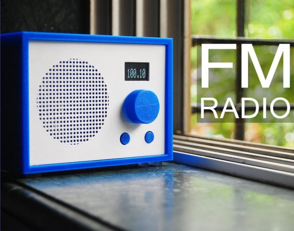
An OLED Display will be used to show the frequency at which it is tuned in.
The output audio signal of the radio module is very low and is not sufficient to drive a 0W speaker. PAM8403 module will be used to amplify the audio signal. There are many versions of this module. I went with the one which has a pot for volume control as well as ON/OFF switch.
Step 2: Preparing the FM Radio Module
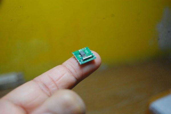
As you can tell by looking at the picture, it is very, very tiny! On top of that, the pad spacing of the module is not breadboard/perfboard friendly.
We have to make a breakout board for it. Cut a small piece of perfboard about the size of the module. Make sure there are at least 5 holes on each side. Solder male header pins as shown in the picture. Next, place the module on the board and solder thin wires between pads on the module and header pins. I used the trim outs of the component legs.
Step 3: Making the Enclosure

I am completely new to 3D designing and this is by far the most I have designed. The enclosure is designed in Fusion 360 and printed on Creality Ender 3 printer. I have attached all the .STL files which I have used.
I painted the Front Plate in white as I have only one color of filament.
I inserted the ‘M3 Threaded Inserts’ in the holes on the outer body using a soldering iron. It was quite satisfying!
Glue the Inner Rim inside the Outer Body using super glue.
Also, make a 6mm and 2mm hole in the ‘Back Plate’ for the knob of the amplifier and antennae respectively. I forgot to add those while designing.
Read more: FM Radio