Summary of Flash trigger using arduino
This project adapts a Glaciar Wanderer concept to trigger a camera flash using an Arduino. The author replaces the microphone sensor with a transistor-controlled laser and employs a 4N26 optocoupler to safely isolate high-voltage flash signals from the microcontroller. This setup allows for future expansion to multiple lasers while protecting the Arduino from potential voltage damage.
Parts used in the Flash Trigger Project:
- Arduino board
- Laser
- Transistor
- 4N26 optocoupler
- Vivitar 285HV flash
- Hotshoe-to-pc-sync adaptor
- Camera
- Flash trigger module
his project is mainly based in this one from Glaciar Wanderer. I just liked his idea and worked it on my own. (I think this guy and me would be friends, as the projects he has in his photography category are things I’ve been wanting to do since I got my Arduino.
 I will not be using a microphone as sensor, at least not right now. On the other side I am using a transistor to control the laser instead of using a digital output of the arduino board directly, as I pretend to use more than one laser, and using a transistor will allow me to draw more milliamps than the Atmel chip can provide.
I used a 4N26 optocoupler to trigger the flash, connected to a hotshoe-to-pc-sync adaptor in my Vivitar 285HV. Using an optocoupler you get sure that no current from the arduino will go to the flash, and no current from the flash will go to the arduino. Anyway, you should check the trigger voltage of your flash, as if it has a high voltage (even hundreds of volts) it could damage the optocoupler and everything that is connected to it (arduino, computer, you…).
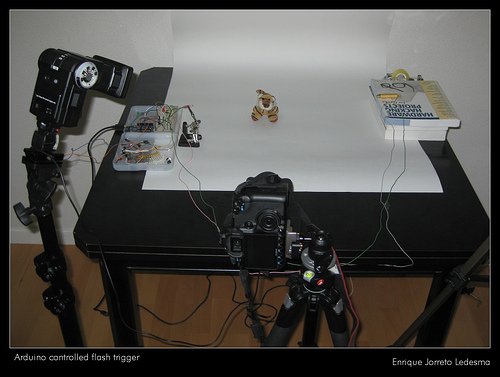
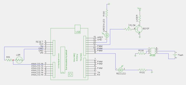 In the 285HV the center pin is the “live” one, thus it is connected to pin 5 of the 4N26, you should check this in your flash, as I think some brands have this “swapped”. For this I used my camera and flash trigger module
For more detail: Flash trigger
- Why is a transistor used instead of a digital output?
A transistor controls the laser to allow drawing more milliamps than the Atmel chip can provide, enabling the use of multiple lasers. - What component triggers the flash in this project?
The 4N26 optocoupler is used to trigger the flash connected to a hotshoe-to-pc-sync adaptor. - How does the optocoupler protect the circuit?
It ensures no current flows from the Arduino to the flash or vice versa, preventing damage to the microcontroller. - What risk exists if the flash has high voltage?
High voltage could damage the optocoupler and everything connected to it, including the Arduino and computer. - Which pin on the Vivitar 285HV is the live one?
The center pin is the live one and should be connected to pin 5 of the 4N26. - Do all flash brands connect pins the same way?
No, some brands may have the pins swapped, so you must check your specific flash model.