
Summary of 6 Volt 5 Watt solar charge controller
This article describes a custom 6V 5W solar charge controller project. It utilizes a dedicated PCB for power management, handling PV protection, voltage/current sensing, and load switching, while relying on an external Arduino Pro Mini for firmware execution. The board features reverse polarity protection, MOSFET-based back-feed and load control, and multiple connector options for flexible load configurations.
Parts used in the 6 Volt 5 Watt solar charge controller:
- Custom printed circuit board
- External Arduino Pro Mini
- PV input transient protection
- Reverse polarity protection
- Dedicated MOSFET for PV back feed
- PTC fuse
- Load current sensors
- Battery voltage sensors
- Solder jumpers for load configuration
Introduction
The project use a custom printed circuit board for the charge controller power management electronics, and requires an external Arduino pro mini to run the control firmware.
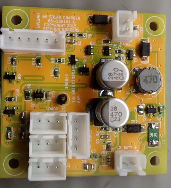 The power management board design has the following features:
- PV input transient and reverse polarity protection
- Sensing for PV input voltage, converter output current, load current, and battery voltage.
- PV Back feed protection using a dedicated MOSFET.
- PTC and reverse polarity protection on the battery connector.
- 3 sets of 3 pin connectors for loads.
- 4 pin sense connector for current and voltage sensing to the Arduino
- 6 pin control connector for control signals from the Arduino
- Dedicated MOSFET for load switching.
- Switched and unswitched load configuration using solder jumpers.
- Double sided circuit board 5cm X 5cm
Firmware
The firmware is hosted as a separate project on my github pages. See fw-6volt-5W-solar-cc. For more details on the firmware features, please visit the firmware page.
For more detail: 6 Volt 5 Watt solar charge controller
- What hardware is required to run the control firmware?
The project requires an external Arduino Pro Mini to run the control firmware. - How does the design protect against PV input transients?
The power management board design includes PV input transient protection. - Does the board support reverse polarity protection?
Yes, the design features PV input reverse polarity protection and PTC plus reverse polarity protection on the battery connector. - What components are used for PV back feed protection?
A dedicated MOSFET is used for PV back feed protection. - Can the loads be configured as switched or unswitched?
Yes, the board supports switched and unswitched load configuration using solder jumpers. - How many sets of connectors are provided for loads?
There are 3 sets of 3 pin connectors available for loads. - What dimensions does the circuit board have?
The circuit board is a double sided design measuring 5cm by 5cm. - Where can I find details about the firmware features?
More details on firmware features are available on the github pages project fw-6volt-5W-solar-cc.
