I don’t have to introduce your colleague, Richard. He is The Backbone of the society. Hard worker, everyone knows he is busy all day. He gets all the praise. But you know the truth. And only you.
He is hardly working. All he does is roam around with a folder with empty sheets of papers. When he “works”, he asks everyone favors, outsourcing his tasks or ask “How would you do this?”. Copy-paste from stackoverflow tops. In addition he never refills the water or empty the grounds in the coffee machine. He broke the leader’s mug. Never changed the water dispenser’s bottle. He leaves skidmarks and never washes his hand. And the list goes on.
Dick has to be punished. This gift can be your sweet revenge!
Disclaimer: Don’t. Just don’t. First of all, of course you will be caught and everyone will be sorry for Dick and will hold a grudge against you for. Pranking a friend? That’s OK. But you will have to find other ways to find revenge. Maybe lataxive wink-wink.
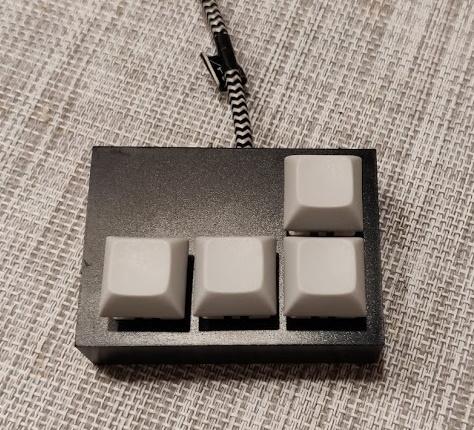
A regular macropad would have been boring, so add a little twist. If you love gambling, this will be your favourite work companion! Will it work this time or mess up everything? The suspense will keep you excited!
Of course you can “downgrade” to a regular macropad, but hey! It’s always possible to spice things up.
Supplies
ATtiny85-20S or a Digistump board
Cherry MX (or compatible) switches
Plastic instrument box / enclosure
USB cable
Step 1: Mother of All Mess
Since we are currently facing unprecented semiconductor-shortage, most of you (me too) will order modules from shady shops. “Aftermarket” Arduinos and devboards were just cheaper back then, but even the big guys like Farnell, Digikey, Mouser or TME have empty stocks, we have no other choice. What a bummer.
And those aftermarket boards always had some tricks up in their sleeves.
The next paragraph is for those, who use a Digistump module as-is.
Sometimes it’s a design mistake. The LEDs on the pins in this case cause a big problem, namely if we try to use the pull-up resistor + switch connecting to ground technique (which is “the standard” method) to detect keypress, the LED will always drive the pin low (not ground, but the microcontroller will detect it as ground). Desolder the user LED. (the power LED is OK)
The next paragraph is for those, who use a Digistump module or desolder the MCU from the module.
Since this microcontroller has 8 pins, we have to cut some corners. 2 of them are power pins, 2 used for USB, 4 left. We have to utilize the reset pin too! Sadly, I ran into misconfigured aftermarket modules, and I had to disable the reset manually. You will have to do too. I ran into this excellent tutorial which describes how to check and correct the mistake.
Step 2: Hardware Assembly
Since the custom PCB failed to arrive in time, we explore the DIY version only. Most of you will need a DIY version anyway!
The circuit and PCB design is freely available here, so feel free to order some, because it’s probably more expensive if I send you one. (But you can still PM me if I have some spare left, maybe I’ll sell it on Tindie, who knows?)
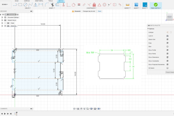
The DIY edition will need the enclosure, that will hide all the electronics and wiring while holding the switches. The mounting dimensions of the switches are public, I designed an L shaped keypad. If you want to do the same, just download the .svg, ask someone with a laser cutter to cut it out and you are good to go. You can get a file too and spend hours filing, you decide. But always check the final dimensions! I did a paper test, then got some scrap acrylic. Premade boxes aren’t expensive, but of course you will order only one, why more? Test (measure) twice, cut once!
And drill one hole for the USB cable. That’s all. If you want to make it fancy, grab some rubber pads/feet.
Attachments
Step 3: Circuit Assembly
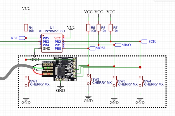
The circuit is fairly easy.
The microcontroller will utilize the builtin pull-up resistor to drive the pin to high level, and connect one switch to each pin. (5, 2, 1, 0, the others are in use) Connect the other pin of the switches to ground. That’s it! No multiplexing, no shift register magic via SPI. Keep it simple this time.
Step 4: Electronics, Second Half
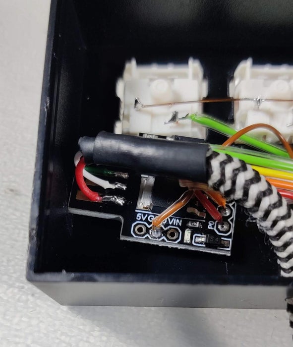
Now behead the USB cable and strip the wires.
How to remember the color codes of USB? Simple: the Hungarian and Italian flag + black. Red, white, green.
It’s tempting to solder the USB D- and D+ (white, green) wires to pin 4-3 directly. DON’T. It looks nasty, I know, but it’s a must to use the USB port’s pins. There are some extra components which make USB-compatible voltage levels, and those are “bypassed” on pin 4-3. Don’t fry your computer.
Fix the Digistump, preferably with a double-sided tape. Last but not least, prevent the USB cable from slipping out with a zip tie.
Now you can close the enclosure.
Step 5: Commands
You can grab the source code from my GitHub page. If you have installed Arduino IDE and installed the Digistump boards, open the code and think about: what shortcuts are needed?
Quick explanation: the DigiKeyboard.sendKeyStroke() function sends the “I pressed this button” message. Most of the single keys like letters and numbers are called KEY_X or similar. The “not so trivial” keys are listed in the key_definitions.h file. Calling this function will look like this: DigiKeyboard.sendKeyStroke(KEY_X);
Of course you will need combos, like Ctrl+C. The DigiKeyboard.sendKeyStroke(KEY_C, MOD_CONTROL_LEFT); will do the trick. If you want to press multiple modifiers, do some binary OR, the famous Ctrl+Alt+Del looks like this: DigiKeyboard.sendKeyStroke(KEY_DELETE , MOD_CONTROL_LEFT | MOD_ALT_LEFT);
I tried to make it as understandable as possible. Search for “commands for key” to navigate in the code. Stuff after // are ignored, called comments.
Step 6: How Evil Are You?
We ask Fortuna for help and utilize random numbers to decide the user’s fate after each keystroke.
You can turn off the evil functions for each key by deleting or commenting (put // before it, remember?) the #define EVIL_X.
But if you left it enabled (and configured to do something nasty) you must fine-tune the chances.
Arduino’s random() function generates a number between 0 and a given number. Increasing the number will decrease the chance. For convenience I made 4 macros (that’s how the #define-s are called) namely #define EVIL_X_CHANCE. Simple: It must be at least 1, meaning 1/1=100% chance. Set it to 5: 1/5=20% chance. It’s NOT a counter but a RANDOM number generator, so it’s possible that it happens seemingly much more often. Also it must be about 2 billion tops, but it would be like winning the lottery.
Oh, and “Evil commands for key X” mark where you should put your commands. You can even run a sequence of keystrokes.
Step 7: Conclusion
This project can be a fine practical april’s fool joke or a harmless and cheap streamdeck alternative. You decide.
Practical use cases are welcome, it may be added to the official documentation as a template. Just write it in the comments!
Source: Evil Macropad