A friend of mine is a scientist who does experiments that are very sensitive to air temperature and humidity. The incubator room has a small ceramic heater but the heater’s thermostat was not nearly accurate enough, only able to maintain the temperature within 10-15 degrees.
Commercial devices that log temperature and humidity can be quite expensive, and getting the data from the device can be difficult. Plus, they can’t control the temperature, only log the data. He asked how hard would it be to build a device that could accurately control the heater through a relay while logging the temperature and humidity. Sounded easy enough.
Grabbing an ESP8266, relay, DHT22, and some online IoT platform, we’re off.
Step 1: Supplies
This project uses a handful of supplies, all of which are pretty common and you may already have them on-hand today. Here is a full list of what I used, feel free to adjust as needed to meet your project needs.
- ESP8266 ESP-01 (or similar ESP8266 board)
- DHT-22 Temperature and Humidity sensor
- LM317 variable voltage regulator (or a standard 3.3V regulator would be easier)
- 5V High current relay (I started with a 10A but did blow it out within 2-days)
- Various resistors and capacitors
- Jumper wires
- Standard electrical outlet and cover
- Electric Gang box
- Old USB plug with adaptor
- Old electrical plug
In retrospect, using a NodeMCU instead of the ESP-01 would have made a lot more sense. I didn’t have one at the time so I made do with what I had on hand.
Step 2: Outlet Construction
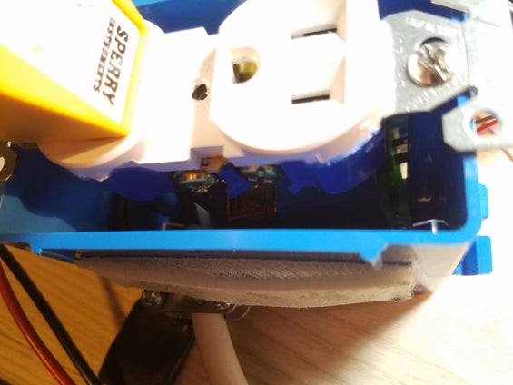
While I technically started with the micro-controller and code, it makes sense to start with the AC outlet first. For this project, I used a single gang box, a standard 2-plug outlet, and the power cord from an old power strip.
The electrical socket gets wired up with the two white wires joined together and the two ground wires joined together. The two black wires going through the high-side of the relay. Make sure you get the terminals screwed down well and none of the strands are going to short out, I put a little solder on the wires so that the stands stayed together.
Be careful with the high-voltage and double check each connection. It is a good idea to put electrical tape on your wire lungs so they don’t wiggle loose.
Step 3: Curciut Design
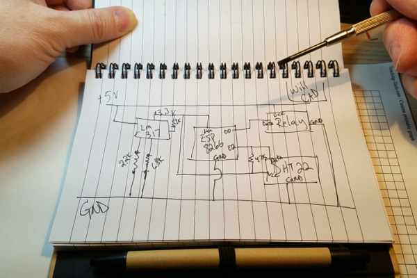
The circuit is pretty straightforward but if you use the ESP-01 as I did, you will need to add a voltage regulator to get a 3.3V. Standard relays do require 5V so you’ll need a 3.3V and 5.0V rail.
My circuit used an LM317 voltage regulator with a set of resistors to get a constant 3.3V rail, I tapped the USB 5V to power the relay. There are 3.3V relays but not for high-current relays needed if you are going to power a small space heater.
The DHT22 requires a 4.7k pull-up resistor.
Step 4: Solder the Board
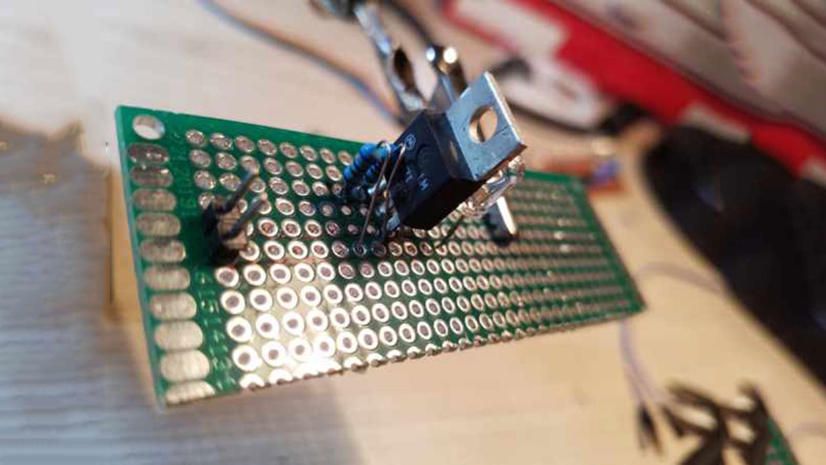
Layout and solder all of the components. This can be a bit tricky but pre-plan the traces with a piece of graph paper will help.
I used a USB board for a power plug but it was a pretty weak and replaced it with two header pins instead. I used two female headers on the board and soldered two male-header pin directly to an old USB plug. This proved to be more reliable and solid. The USB wiring colors are:
Black –> Ground
Red –> 5V
I also used male headers to expose the DHT22 and Relay pins on my perfboard to connect them with standard jumper wires.
Make sure you label each pin, power and ground connector in case it gets unplugged later.
Source: ESP8266 Temperature Controlled Relay