This is a small dev board I designed to make experimenting with and deploying the ESP8266 ESP-03 modules a bit easier. As well as breaking out all the pins to 2.54mm headers it has a position to fit either a DS18B20 temperature sensor or a DHT22 temperature/humidity sensor plus the required pull up resistor. It can be powered from 3.3V or 5V+* if the regulator is fitted and there is a footprint for a micro USB connector if required.
*The regulator I used is good for up to 18V but I don’t know how far you would be able to push it with only the small area of PCB that is used as a heatsink. I would imagine it will be OK to at least 9V.
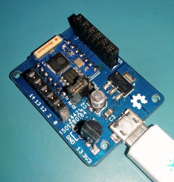
A 3 way pin header allows a jumper to be moved to switch between normal running mode and flash programming mode. With the jumper in the RUN position GPIO0 is connected to the header marked 0 and in the PRG position GPIO0 is grounded. It needs to be powered up with the jumper in the PRG position to enable programming mode.
Side note: to use the deep sleep function of the ESP8266 you must link two pads on the ESP-03 module itself, the ones near VCC and GPIO14 (see picture on left). This joins GPIO16 to RST on the chip so it can be woken up automatically, this is the only way to do it with the ESP-03 as RST isn’t broken out on the module.
For more Details: ESP8266 ESP-03 Dev Board