Summary of ESP32 NTP Temperature Probe Cooking Thermometer With Steinhart-Hart Correction and Temperature Alarm.
This article details the construction of an ESP32-based cooking thermometer featuring NTP temperature sensing, Steinhart-Hart correction for accuracy, and a programmable alarm. The project utilizes capacitive touch buttons for interface control, a piezo buzzer for alerts, and a custom 3D-printed case. It covers mathematical calibration methods, hardware assembly using specific resistors and probes, and software installation via Arduino IDE.
Parts used in the ESP32 NTP Temperature Probe Cooking Thermometer:
- ESP32 WiFi Kit 32
- NTP temperature probe (Maverick ET-72)
- Piezo buzzer (square wave driven)
- 2.5mm phone connector (panel mount)
- 33k ohm 1% 1/8 watt resistor
- Five 4-inch pieces of 28awg wire (red, black, yellow, two green)
- OLED display
- Capacitive touch input components (Metallic Hole Plugs)
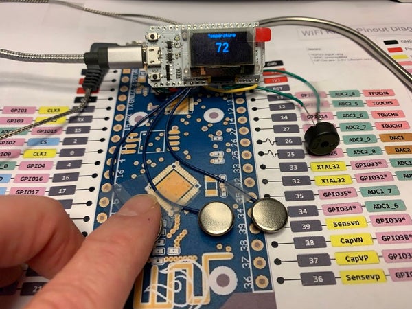
Still on the journey to complete an “upcoming project”, “ESP32 NTP Temperature Probe Cooking Thermometer With Steinhart-Hart Correction and Temperature Alarm” is an Instructable showing how I add an NTP temperature probe, piezo buzzer and software to my capacitive touch Instructable “ESP32 Capacitive Touch Input Using “Metallic Hole Plugs” for Buttons” to create a simple but accurate cooking thermometer with a programmable temperature alarm.
The three capacitive touch buttons allow the temperature alarm level to be set. Pressing the center button displays the “Set Alarm Temperature” display, enabling the left and right buttons to reduce or increase the alarm temperature respectively. Pressing and releasing the left button will reduce the alarm temperature one degree, while pressing and holding the left button will continuously reduce the alarm temperature until released. Similarly, pressing and releasing the right button will increase the alarm temperature one degree, while pressing and holding the right button will continuously increase the alarm temperature until released. When finished adjusting the alarm temperature, simply touch the center button again to return to the temperature display. At any time the temperature is equal to or higher than the alarm temperature, the piezo buzzer will sound.
And as mentioned, an NTP temperature probe is used in the design along with the Steinhart-Hart equations and coefficients necessary for accurate temperature readings. I’ve included an overly-verbose description of the Steinhart-Hart equation, the Steinhart-Hart coefficients, voltage dividers and algebra in Step 1 (as a bonus, it puts me to sleep every time I read it, so you may wish to skip Step 1 and head straight to Step 2: Assembling the Electronics, unless of course you need a nap).
If you decide to build this cooking thermometer, for customization and 3D printing I’ve included the following files:
- Arduino file “AnalogInput.ino” containing the software for the design.
- Autodesk Fusion 360 cad files for the case showing how the case was designed.
- Cura 3.4.0 STL files “Case, Top.stl” and “Case, Bottom.stl” ready for 3D printing.
You will also need familiarity with the Arduino environment as well as soldering skills and equipment, and in addition may need access to accurate digital ohmmeters, thermometers and temperature sources for calibration.
And as usual, I probably forgot a file or two or who knows what else, so if you have any questions, please do not hesitate to ask as I do make plenty of mistakes.
The electronics were designed using pencil, paper and a Radio Shack EC-2006a (Cat. No. 65-962a) solar powered calculator.
The software was designed using Arduino 1.8.5.
The case was designed using Autodesk Fusion 360, sliced using Cura 3.4.0, and printed in PLA on an Ultimaker 2+ Extended and an Ultimaker 3 Extended.
And one final note, I receive no compensation in any form, including but not limited to free samples, for any of the components used in this design
Step 1: Math, Math and More Math: Steinhart–Hart, Coefficients, and Resistor Dividers.
My earlier designs incorporating an NTC temperature probe used a table lookup technique for converting the incoming voltage from a resistor divider to temperature. Since the ESP32 is capable of twelve bit analog input, and since I was designing for increased accuracy, I decided to implement the “Steinhart-Hart” equation in the code for voltage to temperature conversion.
First published in 1968 by John S. Steinhart and Stanley R. Hart, the Steinhart-Hart equation defines the resistance to temperature relationship of an NTC temperature probe as follows:
1 / T = A + (B * (log(Thermistor))) + (C * log(Thermistor) * log(Thermistor) * log(Thermistor))
where:
- T is degrees Kelvin.
- A, B, C are the Steinhart-Hart coefficients (more on that in a moment).
- And Thermistor is the temperature probe thermistor resistance value at the current temperature.
So why is this seemingly complicated Steinhart-Hart equation necessary for a simple NTC temperature probe based digital thermometer? An “ideal” NTC temperature probe would provide a linear resistance representation of the actual temperature, thus a simple linear equation involving voltage input and scaling would result in an accurate temperature presentation. However, NTC temperature probes are not linear and, when combined with the non-linear analog input of virtually all low cost single board processors such as the WiFi Kit 32, produce non-linear analog inputs and thus inaccurate temperature readings. By using an equation such as Steinhart-Hart along with careful calibration, highly accurate temperature readings using NTC temperature probes with a low cost single board processor can be attained by generating a very close approximation of the actual temperature.
So back to the Steinhart-Hart equation. The equation utilizes the three coefficients A, B and C to determine temperature as a function of the thermistor resistance. Where do these three coefficients come from? Some manufacturers provide these coefficients with their NTC temperature probes, and others do not. Furthermore, the manufacturer provided coefficients may or may not be for the exact temperature probe you may purchase, and are most likely coefficients representative of a large sample of all temperature probes they manufacture over a period of time. And finally, I simply could not locate the coefficients for the probe used in this design.
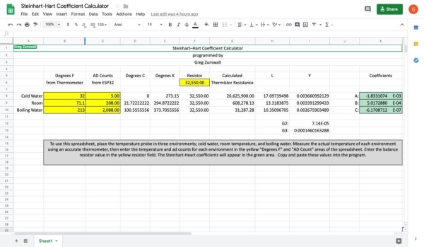
Without the needed coefficients, I created Steinhart-Hart Spreadsheet , a spreadsheet based calculator that assists in generating the needed coefficients for an NTC temperature probe (I lost the link to a similar web based calculator I used many years ago, so I created this one). To determine the coefficients for a temperature probe, I start by measuring the value of the 33k resistor used in the voltage divider with a digital ohmmeter, and enter the value into the yellow area of the spreadsheet labeled “Resistor”. Next, I place the temperature probe in three environments; first room temperature, second ice water and third boiling water, along with a known accurate digital thermometer, and allow time for the temperature on the thermometer and the thermistor input count appearing on the WiFi Kit 32 display (more on this later) to stabilize. With both the temperature and thermistor input count stabilized, I enter the temperature indicated by the known accurate thermometer and the thermistor count appearing on the display of the WiFi Kit 32 into the yellow area of the spreadsheet labeled “Degrees F from Thermometer” and “AD Count from WiFi Kit 32” respectively, for each of the three environments. Once all measurements are entered, the green area of the spreadsheet provides the A, B and C coefficients required by the Steinhart-Hart equation that are then simply copied and pasted into the source code.
As previously mentioned the output of the Steinhart-Hart equation is in degrees Kelvin, and this design displays degrees Fahrenheit. Conversion from degrees Kelvin to degrees Fahrenheit is as follows:
First, convert degrees Kelvin to degrees Celsius by subtracting 273.15 (degrees Kelvin) from the Steinhart-Hart equation:
Degrees C = (A + (B * (log(Thermistor))) + (C * log(Thermistor) * log(Thermistor) * log(Thermistor))) – 273.15
And second, convert degrees Celsius to degrees Fahrenheit as follows:
Degrees F = ((Degrees C * 9) / 5) + 32.
With the Steinhart-Hart equation and coefficients complete, a second equation is required to read the resistor divider output. A model of the resistor divider used in this design is:
vRef<—Thermistor<—vOut<—Resistor<—Ground
where:
- vRef in this design is 3.3vdc.
- Thermistor is the NTC temperature probe used in the resistor divider.
- vOut is the voltage output of the resistor divider.
- Resistor is the 33k resistor used in the resistor divider.
- And ground is, well, ground.
vOut of the resistor divider in this design is attached to the WiFi Kit 32 analog input A0 (pin 36), and the voltage output of the resistor divider is calculated as follows:
vOut = vRef * Resistor / (Resistor + Thermistor)
However, as noted in the Steinhart-Hart equation, the thermistor resistance value is required in order to obtain temperature, not the voltage output of the resistor divider. So rearranging the equation to output the thermistor value requires the use of a little algebra as follows:
Multiply both sides by “(Resistor + Thermistor)” resulting in:
vOut * (Resistor + Thermistor) = vRef * Resistor
Divide both sides by “vOut” resulting in:
Resistor + Thermistor = (vRef * Resistor) / vOut
Subtract “Resistor” from both sides resulting in:
Thermistor = (vRef * Resistor / vOut) – Resistor
And finally, using the distributive property, simplify:
Thermistor = Resistor * ((vRef / vOut) – 1)
Substituting the WiFi Kit 32 A0 analog input count of 0 through 4095 for vOut, and substituting the value of 4096 for vRef, the resistor divider equation providing the thermistor resistance value required by the Steinhart-Hart equation becomes:
Thermistor = Resistor * ((4096 / Analog Input Count) – 1)
So with the math behind us, let’s assemble some electronics.
Step 2: Assembling the Electronics.
For the electronics, I had previously assembled the ESP32 Capacitive Touch demonstrator https://www.instructables.com/id/ESP32-Capacitive... With that assembly, the following additional components are required:
- Five, 4″ pieces of 28awg wire (one red, one black, one yellow and two green).
- One, Maverick “ET-72 Temperature Probe” probe (https://www.maverickthermometers.com/product/pr-003/).
- One, 2.5mm “phone” connector, panel mount (https://www.mouser.com/ProductDetail/502-TR-2A).
- One, 33k ohm 1% 1/8 watt resistor.
- One, piezo buzzer https://www.adafruit.com/product/160. If you select a different piezo buzzer make sure it matches the specifications of this one (square wave driven, <= current output of the ESP32).
To assemble the additional components, I performed the following steps:
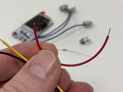
- Stripped and tinned the ends of each 4″ wire length as shown.
- Soldered one end of the yellow wire and one end of the 33k ohm resistor to the “Tip” pin of the phone connector.
- Soldered one end of the black wire to the free end of the 33k ohm resistor and trimmed off the excess resistor wire.
- Applied heat shrink tubing over the wires and resistor.
- Soldered one end of the red wire to the “Sleeve” pin on the phone connector.
- Soldered the free end of the yellow wire to pin 36 on the WiFi Kit 32.
- Soldered the free end of the black wire to the GND pin on the WiFi Kit 32.
- Soldered the free end of the red wire to the 3V3 pin on the WiFi Kit 32.
- Soldered one green wire to one lead of the piezo buzzer.
- Soldered the remaining green wire to the remaining lead of the piezo buzzer
- Soldered the free end of one of the green piezo wires to pin 32 on the WiFi Kit 32.
- Soldered the free end of the remaining green piezo wires to the GND pin on the WiFi Kit 32.
- Plugged the temperature probe into the phone connector.
With all wiring complete, I double checked my work.
Step 3: Installing the Software.
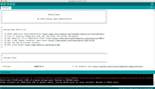
The file “AnalogInput.ino” is an Arduino environment file containing the software for the design. In addition to this file, you will need the “U8g2lib” graphics library for the WiFi Kit32 OLED display (see https://github.com/olikraus/u8g2/wiki for further information on this library).
With the U8g2lib graphics library installed in your Arduino directory, and “AnalogInput.ino” loaded into the Arduino environment, compile and download the software into the WiFi Kit 32. Once downloaded and running, the top line of the OLED display on the WiFi Kit 32 should read “Temperature” with the current temperature displayed in large text in the center of the display.
Touch the center button (T5) to display the “Set Alarm Temperature” display. Adjust the alarm temperature by pressing either the left button (T4) or right button (T6) as described in the introduction. To test the alarm, adjust the alarm temperature to be equal to or lower than the current temperature and the alarm should sound. When finished setting the alarm temperature, touch the center button to return to the temperature display.
The values dProbeA, dProbeB, dProbeC and dResistor in the software are the values I determined during calibration of the probe I used in this design and should generate temperature readings accurate to within a few degrees. If not, or if higher accuracy is desired, then calibration is next.
- How do I set the alarm temperature?
Press the center button to enter the setting mode, then use the left button to decrease or the right button to increase the temperature value. - What equation is used for accurate temperature readings?
The Steinhart-Hart equation is used along with specific coefficients to convert thermistor resistance into temperature. - Can I hold down the buttons to change settings faster?
Yes, pressing and holding the left or right buttons will continuously reduce or increase the alarm temperature until released. - Does the alarm sound when the temperature reaches the limit?
Yes, the piezo buzzer sounds whenever the measured temperature is equal to or higher than the set alarm temperature. - What software environment is required for this project?
You need the Arduino environment version 1.8.5 and the U8g2lib graphics library installed. - How are the Steinhart-Hart coefficients determined?
They are calculated by measuring the thermistor at three known temperatures like room temperature, ice water, and boiling water. - What materials were used to print the case?
The case was designed in Autodesk Fusion 360 and printed in PLA on an Ultimaker printer. - Which pin connects the temperature probe signal?
The yellow wire from the voltage divider connects to pin 36 on the WiFi Kit 32.